
Opening, engagement and panel thickness
Show the mating material thickness and variation, channel opening, engagement depth, relevant radii and any specified adhesive, liner or fixing space.
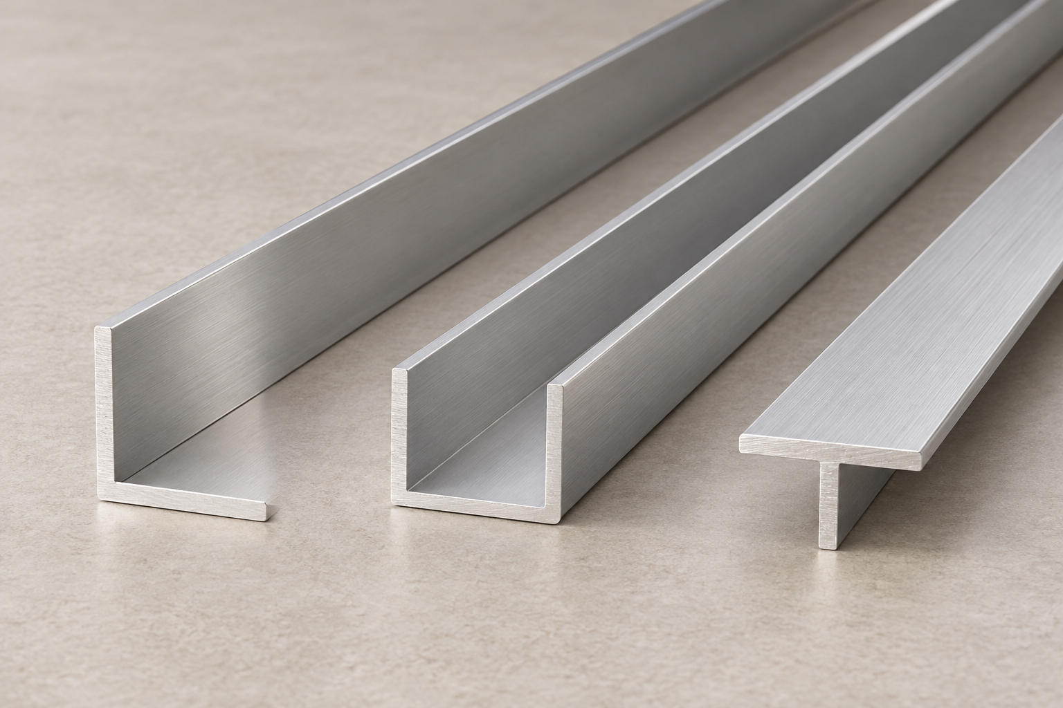
Aluminum trim profiles are extruded sections used to finish exposed edges, cover joints and define corners in panels, furniture and floor or wall coverings. Aluminum Profile Works helps B2B buyers organize a sourcing inquiry around the section drawing, mating material, visible finish and finished supply requirements. The image shows generic trim concepts, not stocked products.
View a trim RFQ exampleTrim profile RFQ example
This hypothetical U-channel panel-edge inquiry shows how to separate defined details from open decisions. It is not a published APW product or a customer project.
Concept illustration only. The generic section shown does not represent a U-channel trim, a manufacturing drawing or an installation detail. Supply your actual dimensioned trim section.
Choose a sourcing path
A shape name is a starting point. Connect the trim section to its actual mating material and installation detail before requesting supply.
Send the cross-section, units, revision and panel or covering thickness. Mark the visible faces and the details still to be confirmed.
View a trim RFQ exampleKeep panel edges, corners and joints connected to the approved architectural detail, fixing method and surface specification.
Explore architectural profilesFor equipment components or fabricated assemblies, start with the industrial sourcing route and define the section's interfaces and processing.
Explore industrial profilesUse these shape descriptions as selection prompts, not as a catalog of confirmed APW products. The actual drawing defines the trim's fit and use.
An L section can cover a corner or form an edge return. Define both leg lengths, wall thickness, corner radius, exposed face and fixing method; a plain angle does not automatically replace a purpose-designed tile trim.
A U channel wraps an edge between two legs; a J section has unequal legs. Match the internal opening and engagement depth to the panel thickness, its variation and any specified adhesive or liner allowance.
A T section can cover a joint with a visible face and locating stem. An H section provides opposed channels for adjacent panel edges. Confirm joint width, stem or channel geometry, fixing and any required movement allowance.
Hydro describes 6063 as a common starting point for appearance-led architectural extrusions with good anodizing response. Specify the alloy and temper for your design, and define the finish, color, gloss, visible faces and approved reference sample. See the Hydro resource below.
Drawing and fit requirements
Provide a cross-section with units, revision and measurement datums. A photograph or L, U or T designation cannot define the required clearance.
Show the mating material thickness and variation, channel opening, engagement depth, relevant radii and any specified adhesive, liner or fixing space.
Dimension the exposed face, corner return, stem or mating channel and intended joint width. Identify the faces that must align or meet the agreed appearance criteria.
List each finished length, end cut or miter, hole position and machining datum. Distinguish continuous extruded geometry from operations added after extrusion.
State critical dimensions and whether they apply before or after finishing. Include visible-surface acceptance, color sample and protection requirements in the supply specification.
This guide gives no universal clearance, wall thickness, tolerance or installation specification. Use the actual material build-up and approved assembly detail.
Resolve fit and finish requirements alongside the section drawing so the inquiry describes the finished part you need.
Nominal thickness alone leaves material variation, finish and fitting allowances unspecified.
Provide the mating material thickness range and specify the finished opening and intended clearance.
A plain angle, panel cap and tile edging profile can have different anchoring and engagement details even when their visible faces look alike.
Compare the full section, installation interface and approved assembly detail.
Lighting and screens do not establish an agreed physical finish, gloss or appearance criterion.
Define the finish and visible faces, and agree a reference sample and acceptance requirements.
Cut ends, machining and packing belong to the finished supply requirement, alongside the continuous extrusion section.
List lengths, end details, processing, inspection and protective packing in the RFQ.
These generated images are generic concept illustrations, not stocked APW products, completed customer projects or approved installation details.
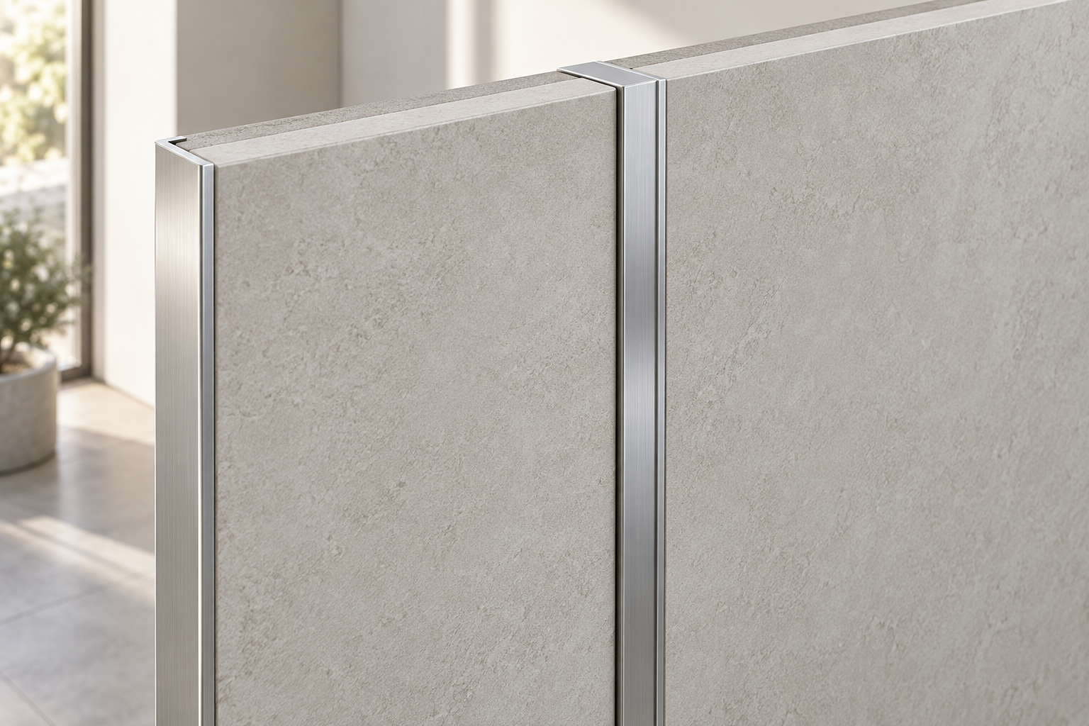
Define panel thickness, edge engagement, visible face, joint width and fixing details for caps, corner returns or connecting sections.
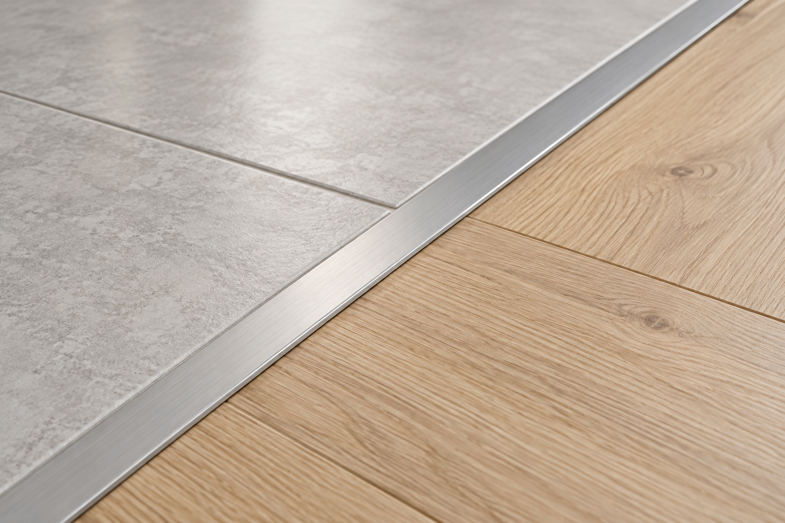
Match the selected profile to covering thickness, adjoining floor level, anchoring and the intended use. Schlüter's tile edging guidance selects profile size by tile thickness; apply the actual product instructions.
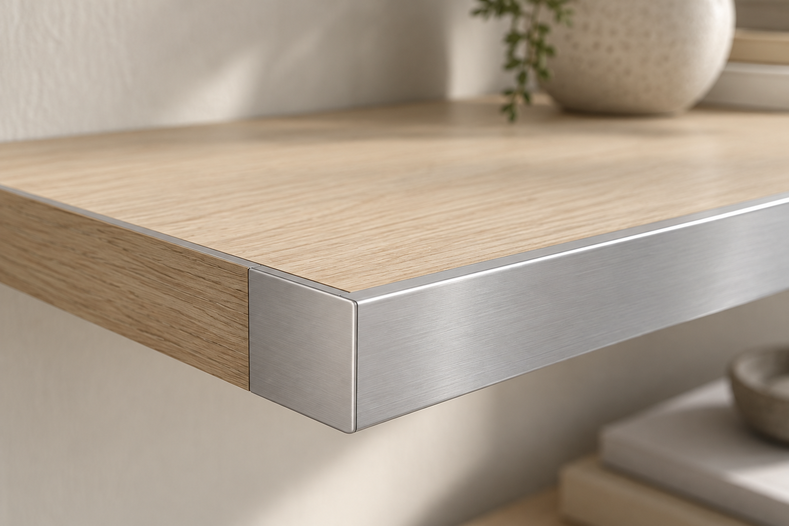
Specify the panel edge, exposed faces, corner joints, finished lengths and fixing method. Confirm the required finish against an agreed reference sample.
Send the information available today and clearly mark unresolved choices. A preliminary drawing or sample reference can begin the discussion.
Keep the section, mating material and finished supply condition together throughout the inquiry.
Send the section drawing or sample reference, intended use, material thickness, finish, quantity and destination where known.
Identify open section dimensions, fixing details, material condition, finish acceptance, cutting, processing and inspection requirements.
Aluminum Profile Works uses the reviewed details to coordinate the supply discussion. Confirm availability, tooling, price, minimum order and delivery terms for the actual inquiry.
These references provide general or manufacturer-specific context. They do not verify APW stock, product compatibility, certification or installation performance.
Background on architectural and appearance-led extrusion applications and anodizing response. Select alloy and temper for the actual design.
A manufacturer's reference for tile-thickness selection and an anodized aluminum edge profile. Its specifications apply to that product, not generic trims.
A reference for preparing aluminum extrusion profile drawings using a uniform method.
Use the actual section and assembly detail to resolve fit, appearance and supply questions.
Send the section and mating detail available today. Aluminum Profile Works will use your application, finish and supply requirements to coordinate the next sourcing discussion.
Your drawing and available details will help frame the inquiry.