
LED Channel Extrusions
LED Channel Extrusion for LED Strip Lighting
Surface, recessed, corner and custom sections
LED strip mounting channels
View profile details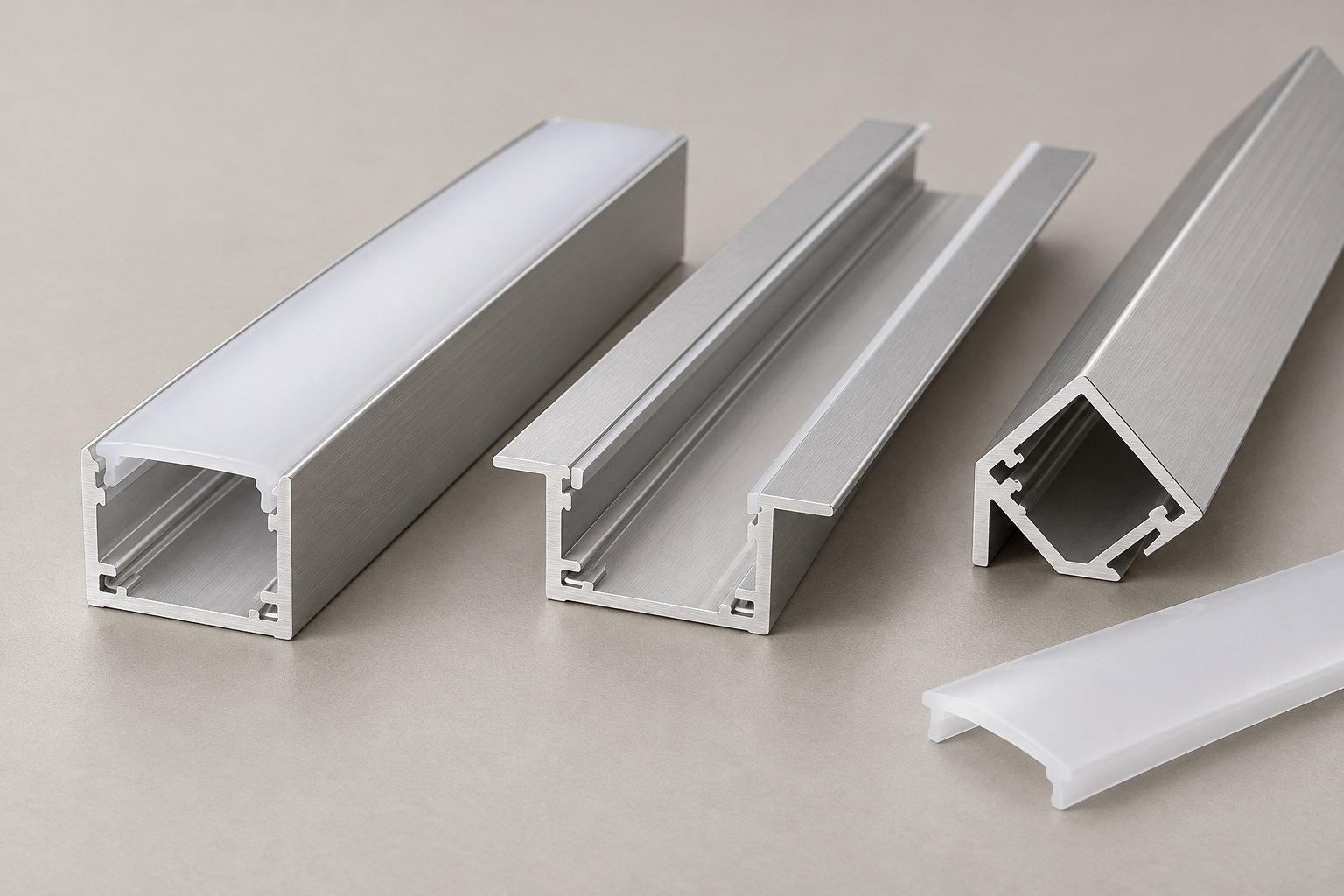
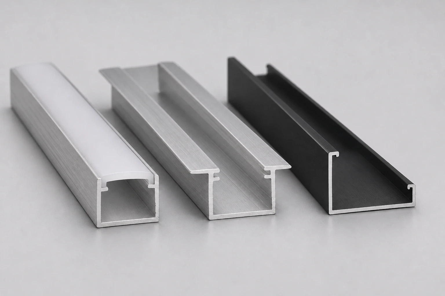
LED aluminum profiles are extruded channels that provide a mounting bed for LED strip lights and an interface for a compatible diffuser. Aluminum Profile Works helps B2B buyers coordinate an extrusion sourcing inquiry around the section drawing, lighting components, mounting detail and finished supply requirements. The image illustrates generic profile concepts.
View an LED profile RFQPublished LED profiles
Check any published section against your drawing and mating components. A drawing or sample reference can begin an inquiry when no matching channel is listed.
Showing 1 of 1 matching profiles
Choose your sourcing path
A channel shape alone cannot define a complete linear lighting assembly. Connect the extrusion drawing to the strip, diffuser and installation interface.
Send the dimensioned drawing or sample reference, strip and connector dimensions, diffuser detail and mounting requirements. Mark unresolved decisions.
View an LED profile RFQFor a lighting component with a defined heat load, include the thermal design requirements and test conditions alongside the extrusion geometry.
Explore extrusion heat sinksConnect recessed edges, mounting flanges and finished surfaces to the approved ceiling, wall or joinery detail.
Explore architectural profilesFor a broader fabricated lighting or equipment component, define the continuous extrusion separately from machining and assembly.
Explore industrial profilesThese are generic LED channel configurations, not a catalog of confirmed APW products. Use the actual section and mounting documentation to establish fit.
A channel mounted onto a surface keeps the extrusion accessible. Specify the mounting footprint, clip or screw interface, visible height, end details and cable exit. Diode LED's channel references below distinguish surface and millwork mounting arrangements.
Define the recess opening, insertion depth, flange width and surrounding material. Keep diffuser access, finished-face alignment and the fixing method visible in the assembly drawing; nominal outer width alone cannot establish recess fit.
For corner lighting, show both mating surfaces and the intended light direction. Confirm the profile angle, mounting clearance and diffuser access against the installation detail rather than selecting from the outside appearance alone.
Specify the suspension interface, connection between lengths, end closures and cable routing. Identify which parts belong to the extrusion inquiry and which belong to the finished lighting assembly; confirm hardware and assembly responsibilities separately.
Fit and drawing checklist
Supply a section drawing with units, revision and measurement datums, plus the mating component references. Distinguish outside channel dimensions from usable internal space.
State the strip width and height, connector or soldered-lead envelope and intended routing. Dimension the usable mounting bed and local clearance at end caps or connections, not only the channel's outside width.
Provide the cover cross-section, retaining lips or grooves, seating position and fit requirements. Identify the LED-to-cover distance. KLUS's line-of-light guidance below explains why cover choice and LED spacing must be considered together.
Show the fixing interface, recess opening and depth where relevant, flanges, adjacent material and access requirements. Use the approved installation detail for the actual assembly.
Dimension the overall section, walls and radii. List finished lengths, end cuts, holes and machining datums separately from the continuous extrusion geometry.
State the specified alloy, temper, finish, color reference and visible faces. Identify whether critical dimensions are inspected before or after finishing, and agree a physical appearance reference.
Provide the strip's power per length, operating conditions and the required thermal acceptance or test method. Request evidence for the actual assembly instead of assuming a channel size establishes acceptable operating temperature.
There is no universal strip clearance, diffuser fit, wall thickness or thermal capacity for every LED extrusion. Use the actual components, assembly drawing and agreed acceptance criteria.
LED profile RFQ example
This hypothetical under-cabinet channel inquiry separates defined interfaces from open supply decisions. It is not a published APW product or a completed customer project.
Concept illustration only. This generic section is not an LED channel drawing or an approved installation detail. Supply the actual dimensioned section with the strip bed, diffuser retention and mounting interfaces.
Keep the aluminum section, mating components and finished supply scope in one clear specification.
A nominal strip width leaves the connector, soldered lead and end-cap space undefined.
Provide the full strip and connection envelope, usable internal bed and cable-routing detail.
Similar-looking covers may have different seating and retention details.
Match the cover section to the channel grooves and agree fit, length and replacement-access requirements.
KLUS identifies cover type, LED spacing, output and LED-to-cover distance as variables in creating a continuous line of light.
Evaluate the actual strip, channel and cover combination against the project's viewing and optical acceptance criteria. See the KLUS reference below.
Extrusion, diffuser, end caps, mounting hardware, machining and electrical components are distinct supply items.
List included and excluded components, fabrication operations and assembly responsibilities in the RFQ and confirm the scope in the quotation.
These generated images are generic concept illustrations, not stocked APW products, completed customer projects or approved installation details.
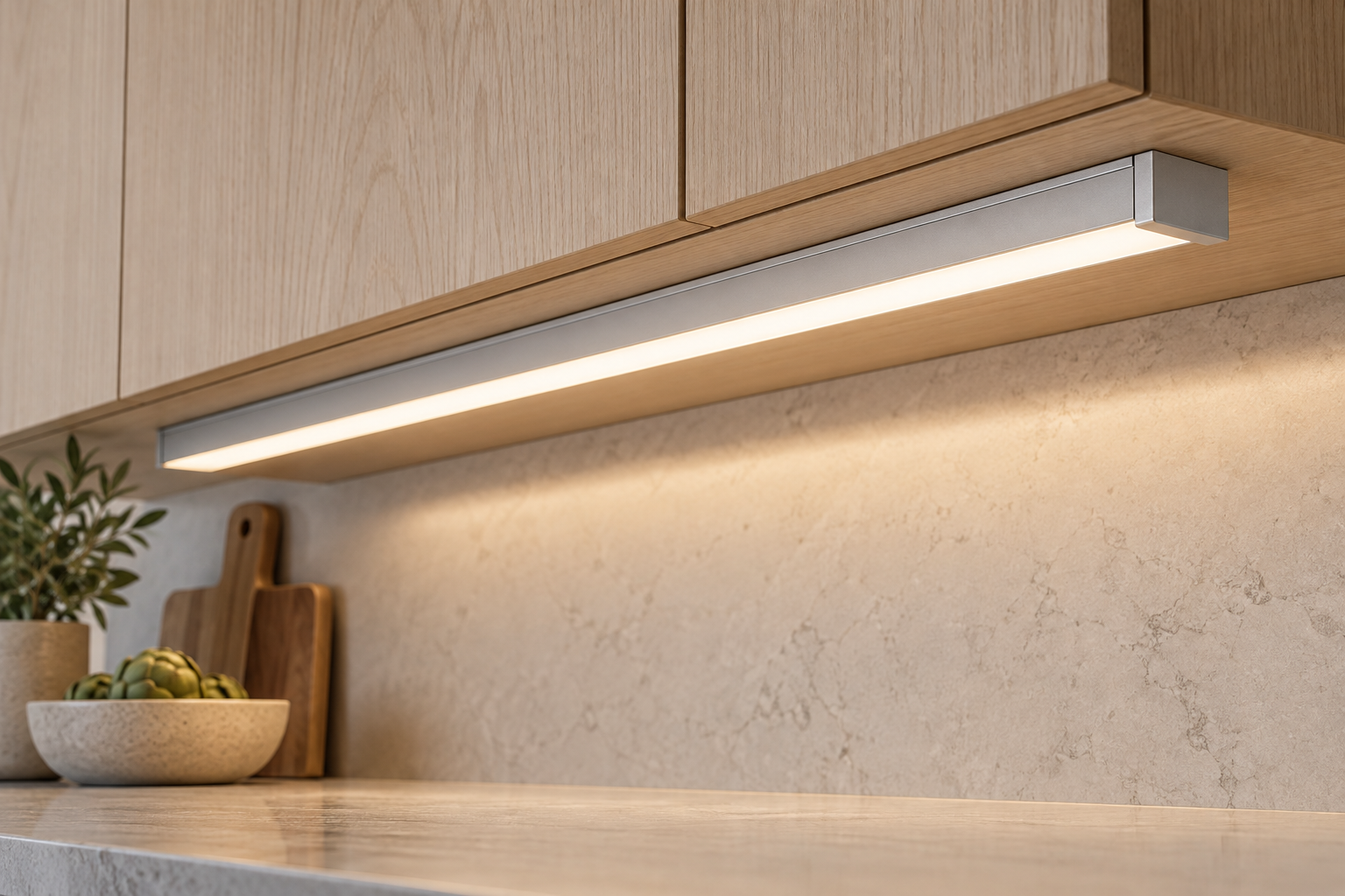
Define the mounting footprint, diffuser access, strip and connector space, end closures and cable exit against the cabinet detail.
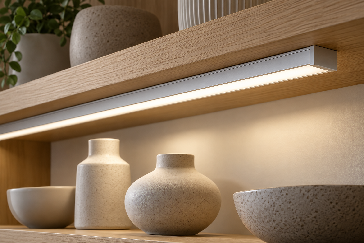
Keep the visible profile finish, light direction, cover choice and shelf interface together. Agree appearance and optical acceptance for the intended viewing position.
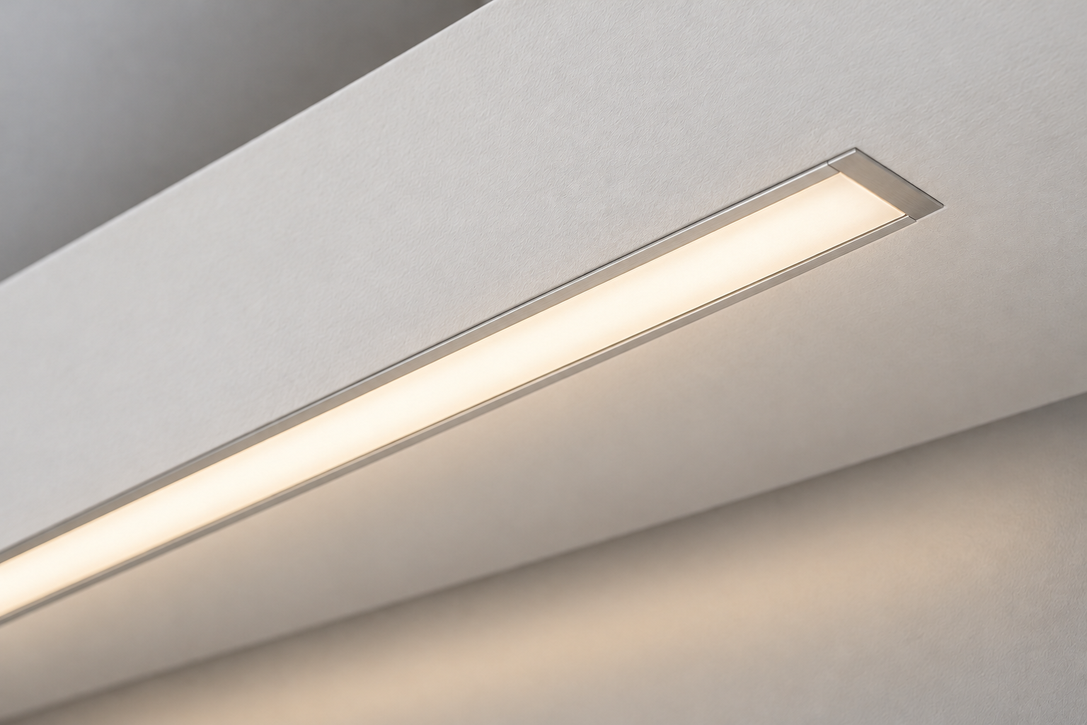
Coordinate recess dimensions, flange width, finished-surface alignment, run connections and maintenance access with the approved interior detail.
Share what is defined today and mark open decisions. Aluminum Profile Works uses these requirements to organize the extrusion sourcing discussion.
Keep extrusion geometry, component interfaces and delivery requirements connected throughout the sourcing conversation.
Share the drawing or sample reference, application, lighting components, finish, quantity and destination where known.
Clarify strip and diffuser fit, fixing details, material condition, dimensional acceptance, machining and assembly validation requirements.
Identify extrusion and processing responsibilities and confirm any accessory requirements separately. Availability, tooling, price, minimum order and delivery terms are confirmed for the actual inquiry.
Discuss finished-length protection, visible-surface protection, identification, packing and export preparation for the agreed supply route.
These references describe other manufacturers' products or general selection principles. They do not verify APW stock, component compatibility, certifications or performance.
Examples of surface, recessed and corner channel configurations and component-dependent diffusion. Specifications apply to the identified manufacturer's products.
A product-specific reference showing aluminum extrusion, lens choices, end caps and mounting components as separate elements of a channel assembly.
Explains the relationship between cover type, LED spacing, output and LED-to-cover distance. Use the actual assembly to evaluate your project's optical requirement.
Start with the extrusion section and the lighting assembly it must support.
Bring your section drawing, strip and diffuser references, installation detail and finished supply needs together. Aluminum Profile Works will use the available specification to coordinate the next sourcing discussion.
Your drawing and available component details will help frame the inquiry.