
Outer envelope and wall thickness
Show overall width and height, section walls and finished length. Identify straightness or twist requirements only where the assembly needs them.
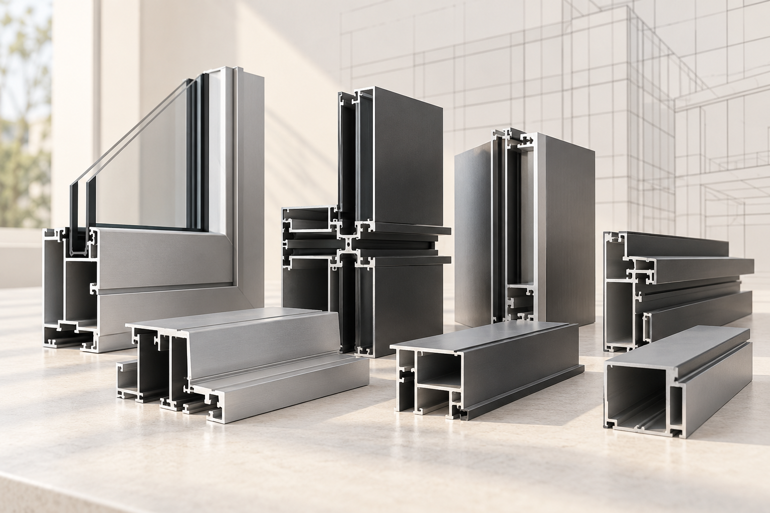
Architectural aluminum profiles are extruded sections used in window and door frames, curtain-wall framing and shading assemblies. Aluminum Profile Works helps buyers coordinate a profile sourcing inquiry around section drawings, mating interfaces, material, finish and finished-part requirements.
Show what is defined and what still needs confirmationArchitectural profile RFQ example
This hypothetical window-frame inquiry illustrates the information to send. It does not describe a published APW product, an approved system or a real project.
Concept illustration only. This generic section is not a window-system profile, a manufacturing drawing, a certified part or an installation detail.
Choose a sourcing path
Use an existing system reference, a dimensioned drawing or a project brief to identify which profile details are defined and which still need review.
Share the section drawing, revision and mating details. Mark critical dimensions and identify what must be supplied after finishing and machining.
Prepare a drawing-led RFQDescribe the intended window, facade or shading assembly and the project requirements already approved by its designer. Record unresolved details for the inquiry.
Discuss the requirementKeep profile geometry, mating parts and finished supply requirements together. Project engineers and system owners must confirm building-envelope performance.
Identify the frame, mullion, transom, louver or other section and show rebates, gasket seats, glazing interfaces, connectors and fixing features where applicable.
Use the alloy and temper specified by the approved design. Hydro identifies 6063 as a common starting point for visible architectural extrusions, but material suitability depends on the application.
Specify anodizing or an organic coating where required, including color or sample reference, exposed faces and the applicable project finish specification.
Separate continuous extrusion dimensions from cut lengths, drilled features and other processing. State critical tolerances, measurement stage and required inspection records.
Drawing and dimension requirements
Send a cross-section with units, datums and revision, plus separate details for finished-part operations. Identify which dimensions apply before or after surface treatment.
Show overall width and height, section walls and finished length. Identify straightness or twist requirements only where the assembly needs them.
Dimension rebates, gasket seats, channels, fixing interfaces and connector engagement surfaces; include mating-part references and critical fit conditions.
Mark the dimensions and inspection points that control assembly fit. Include the approved drawing revision and any changes from a physical sample.
Identify exposed faces, coating or anodizing requirements, cut and hole locations, and whether measurements are required on the unfinished or finished part.
This guide provides no universal tolerances, structural ratings or building-system approvals. Confirm project-specific requirements with the responsible designer and selected system documentation.
An extrusion must be specified as a finished part within its intended assembly. Resolve these questions before treating a section image as a supply specification.
Frame, glazing, gasket, connector and fixing details can depend on features that an overall width does not show.
Share the system or component references, channel and rebate dimensions, critical fits and drawing revision.
A generic alloy name or visual sample does not define the material condition required by the approved design.
State the specified alloy and temper, or mark them for review against the project and fabrication requirements.
Color alone does not define coating type, finish quality, exposure conditions or which surfaces must be protected.
Provide the finish type, color or sample reference, exposure conditions and any applicable project coating specification.
Length, machining, inspection, packing and quantity affect what must be quoted and checked.
List finished lengths, holes or cuts, critical tolerances, required documents, quantities and destination.
These concept illustrations show typical application contexts. They are not stocked APW products, completed customer projects or approved building-system details.
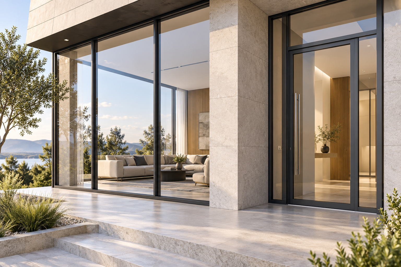
Frames, sashes and related sections need defined glazing, gasket, hardware and corner-joint interfaces. Match each extrusion to the selected system drawing.

Mullion and transom sections connect to glazing, brackets, covers and drainage details. System performance and structural adequacy require project-specific verification.
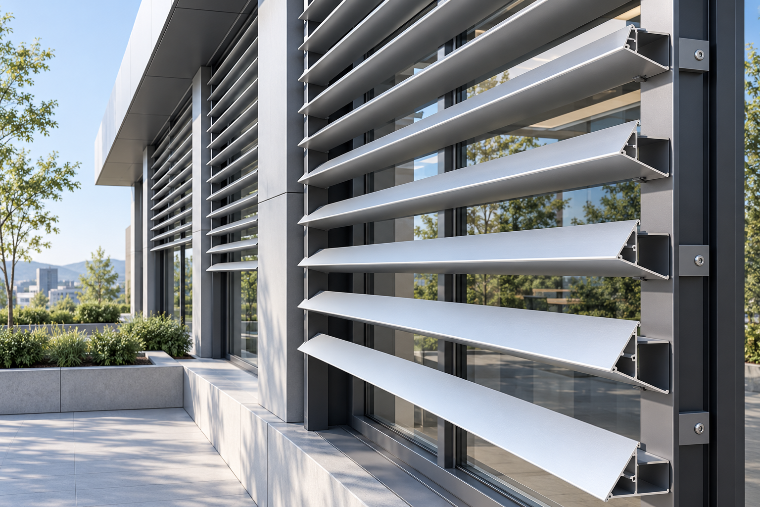
Louver blades and support profiles need defined connection geometry, exposed finish and finished lengths. Wind and fixing requirements belong to the approved assembly design.
A preliminary drawing can start the sourcing discussion. Mark which details are approved and which are still open.
Keep the drawing, mating components and finished supply condition connected through the inquiry.
Send the drawing or profile reference, assembly context and known material, finish, quantity and destination information.
Review missing section dimensions, mating interfaces, processing and inspection needs. Refer system performance and project approvals to the responsible specialists.
Coordinate the supply discussion around the reviewed specification and outstanding questions. Confirm commercial and delivery terms for the actual inquiry.
These external sources provide general technical context. They do not verify APW products, coatings, certifications or complete building-system performance.
General guidance on 6063 extrusion use and visible architectural applications; final material selection belongs to the approved design.
Explains thermal-break joining in aluminum components. Verify the selected assembly and its performance documentation separately.
Introduces the updated AAMA 2603, 2604 and 2605 coating specifications. Specify the applicable edition and verify the actual finish against project requirements.
Describes the quality-label specifications for architectural aluminum coatings; a reference link is not evidence that any supplier holds the label.
Use the selected building-system documents and qualified project review for structural, thermal, weather and installation decisions.
Share the section drawing, mating references and supply details you have today. Aluminum Profile Works will use them to coordinate the next sourcing discussion.
Your drawing and available details will help frame the inquiry.