
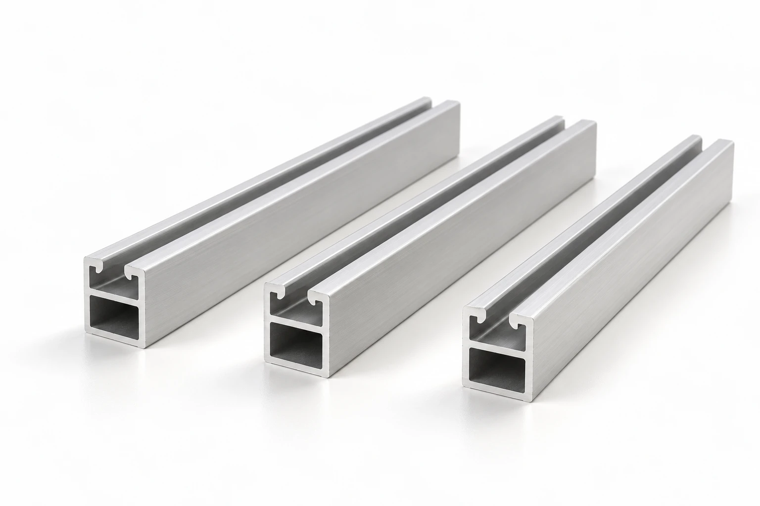
Solar Mounting Rails
Solar Mounting Rail
Standard and custom sections; specify clamp channel, splice cavity, support interface and finished length by drawing
PV module support rail extrusions
View profile details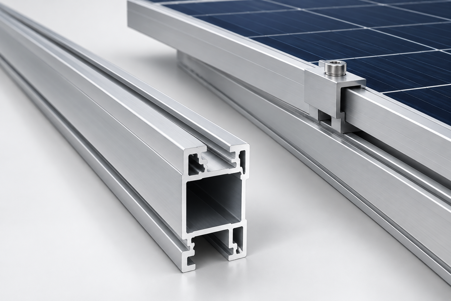
Aluminum solar mounting rails are extruded profiles that support photovoltaic modules within a mounting assembly. Bring the rail section, clamp and splice interfaces, material, finish and supply requirements into one clear RFQ. Aluminum Profile Works helps coordinate the profile sourcing discussion around your drawing and project requirements.
Explore rail profilesPublished solar rail profiles
Use any listed rail profile as a starting point for checking the section and assembly requirements. If no reference matches your drawing, send the available details to begin a sourcing inquiry.
Showing 1 of 1 matching profiles
Choose a sourcing path
The most useful starting point is the information already defined by your mounting-system design. Keep open interface and engineering questions visible during the sourcing discussion.
Compare its section, clamp channel, splice cavity, attachment interface and finished length with the required assembly. Similar outer dimensions do not establish a match.
Explore rail profilesShare a dimensioned section and the mating clamp, splice and support details. Identify critical fits, drawing revision and finished-part requirements.
Prepare a drawing-led RFQDescribe the mounting context, module reference and available design requirements. Record unresolved material, interface and supply decisions for review.
Discuss the requirementUse the rail section and mating-component references together. Mark project requirements separately from dimensions or capabilities that still need confirmation.
Define overall width and height, wall thickness, clamp-channel opening, internal retention surfaces and the module-frame interface. Include mating hardware drawings or part references.
Identify internal or external splice fit, joining features and rail-to-support interfaces. Locate requirements for thermal movement and bonding in the approved mounting-system documentation.
State the roof or ground-mount context, project location and applicable design requirements. Obtain engineering confirmation of loads, support spacing and cantilevers for the complete assembly.
Record the required alloy and temper, surface finish, length, machining, critical tolerances, inspection, packing and quantities. Confirm the supply route against those requirements.
Drawing and dimension requirements
Provide a dimensioned cross-section with units, datums and revision. Separate continuous extrusion features from cutting, drilling and other finished-part operations.
Show overall width and height, wall thickness and critical surfaces. Specify finished length and any required straightness or twist limits rather than assuming them.
Dimension the channel opening, internal width and engagement surfaces. Include the bolt or nut interface and identify fits that must be checked after surface treatment.
Show the splice-cavity envelope, connector engagement and attachment features. Add separate details for machined holes or other features located along the rail.
Specify material, finish, critical tolerances and measurement conditions. Identify whether dimensions apply before or after finishing, and list inspection or material documents required.
This guide sets no universal tolerances, load capacities or installation dimensions. The responsible engineer must confirm the complete mounting design, applicable requirements and validation basis.
Solar mounting rail RFQ example
This hypothetical inquiry shows how to organize a drawing-led RFQ. Its details illustrate an inquiry format, not a published rail specification or approved mounting design.
Concept illustration only. It is not a manufacturing drawing, a dimensional specification, a certified rail or an installation detail.
A rail belongs to an assembly of modules, clamps, splices, attachments and supports. Its drawing and supply specification need to reflect those connections.
A slot width alone does not describe how a clamp bolt, nut or retaining feature engages the rail and module frame.
Provide channel opening, internal engagement geometry, mating hardware reference and the module-frame interface specified by the system designer.
An internal sleeve or external connector needs a defined fit. Rail-to-support connections also need their own interface details.
Show splice-cavity dimensions, joining features and support connections. Refer to the selected system documents for joint locations, movement provisions and bonding details.
Outer width and height alone do not establish an allowable support spacing or suitability for a particular wind and snow environment.
Attach the project design basis and approved system requirements. Have the responsible engineer confirm support spacing, cantilever limits and structural adequacy.
Material, finish, cutting, machining and inspection requirements determine what must be reviewed and supplied against the drawing.
State alloy and temper when selected, finish, cut length, processing, critical tolerances, inspection documents, quantity, packing and destination.
These concept illustrations show general mounting contexts. They are not supplied products, verified customer projects or installation instructions.
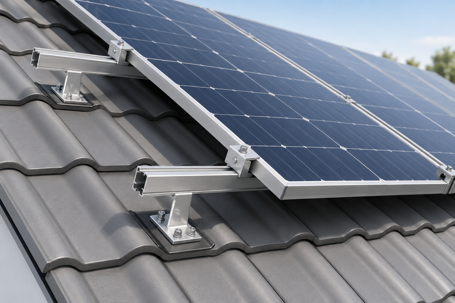
Rail requirements connect the module clamps to the selected roof attachments. Roof construction, attachment details and water management belong to the complete project design.
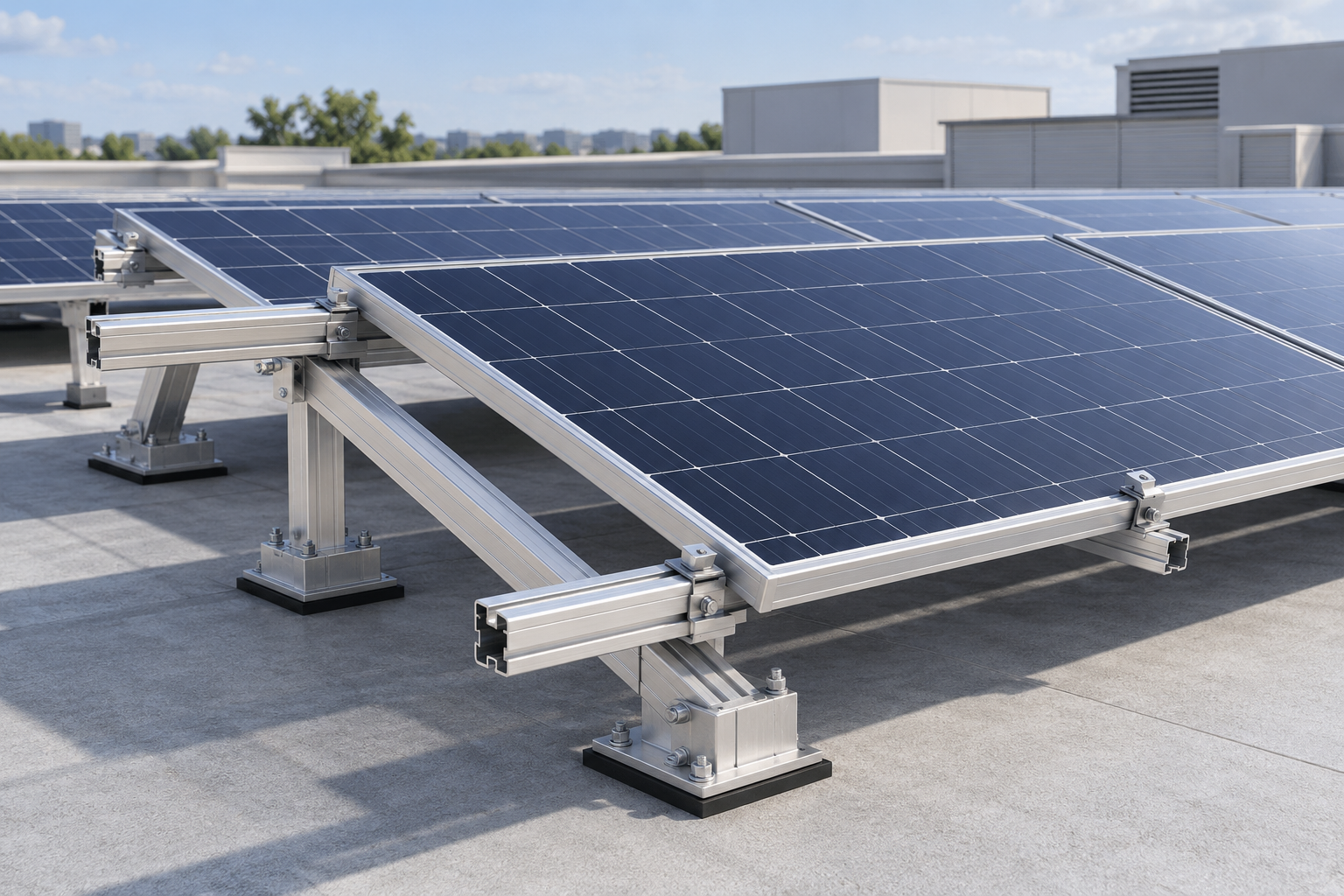
A rail may form the module-support interface within a tilted roof assembly. Define its connection to supports and use the approved system design for roof loading and restraint requirements.
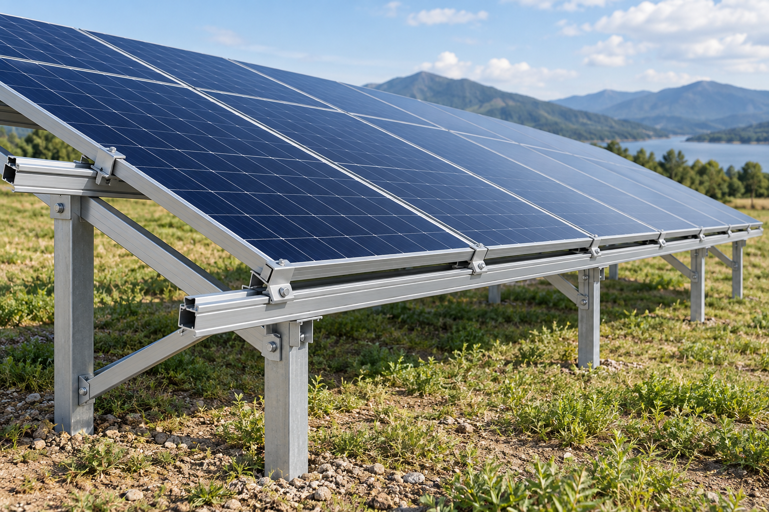
Module-support rails connect to a separate frame and foundation system. Share the rail-to-frame interface, splice arrangement and project requirements established by the system designer.
A preliminary drawing package can start the sourcing discussion. Identify which details are approved and which still require design or supply review.
Keep section geometry, mating interfaces and finished supply requirements connected as the inquiry is reviewed.
Send the rail section, component references and known quantity, processing and destination details. Identify the drawing revision used for the inquiry.
Review unresolved interface dimensions, material, finish, tolerances and inspection needs. Keep structural and system-approval decisions with the responsible project specialists.
Coordinate the supply discussion around the reviewed specification, remaining questions and required supporting documents. Confirm commercial and delivery terms for the actual inquiry.
These external references explain design and documentation topics. They do not establish products, certifications or performance claims for Aluminum Profile Works.
A manufacturer's rail-system example with section options, splice references and project-dependent design documentation. Its specifications apply to the identified IronRidge systems.
Scope information for PV mounting, retention and grounding or bonding components. Use where applicable to the target market and verify the specific evaluated system and module combination.
An entry point for alloy selection, extrusion tolerances, surface treatment, fabrication and machining topics. Registration is required to access the manual.
General guidance for preparing a profile inquiry. Use the selected mounting-system documents and qualified project review for engineering and installation decisions.
Share the section drawing, mating-component references and supply requirements you have today. Aluminum Profile Works will use them to coordinate the next sourcing discussion.
Your drawing and available details will help frame the solar rail inquiry.