
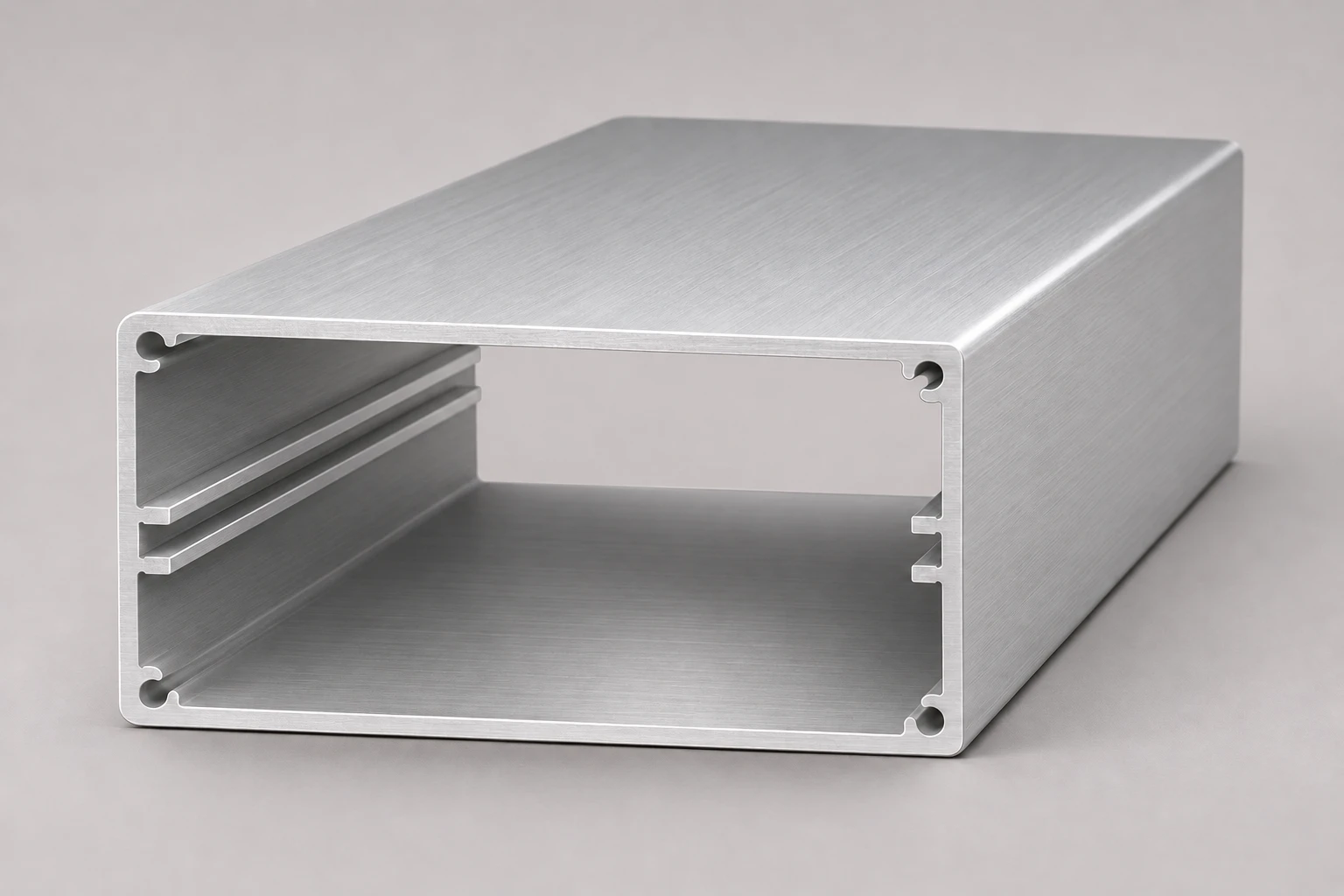
Enclosure Extrusion Profiles
Enclosure Extrusion Profile
Standard and custom sections; define internal clearance, PCB guides, end-panel interfaces and finished length by drawing
Aluminum electronics enclosure bodies
View profile details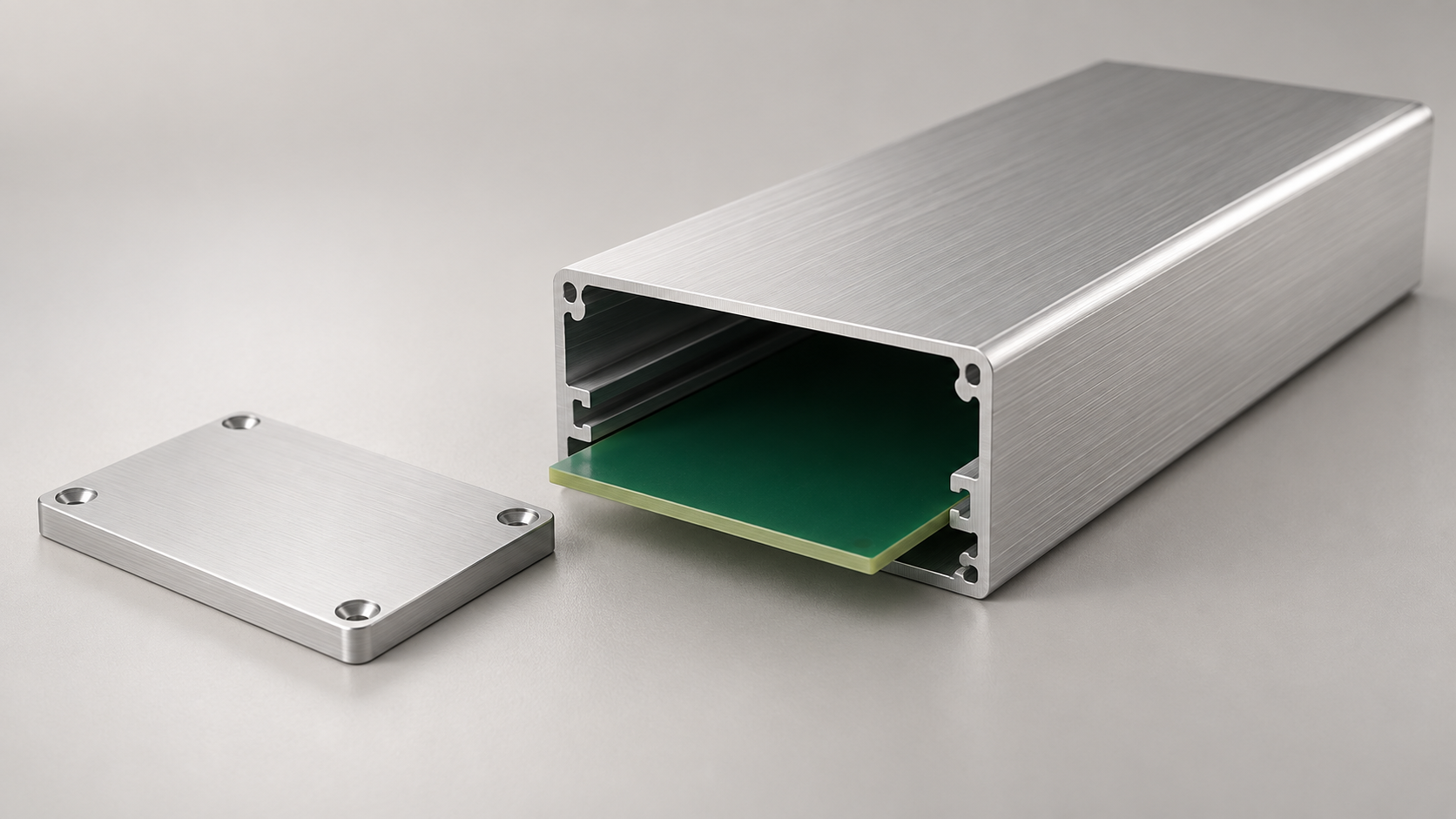
Define an aluminum extrusion profile for an electronics enclosure around its internal clearance, PCB guides, end-panel interfaces and finished-part requirements. Review listed profiles when available or send a drawing to frame an RFQ.
Explore enclosure profilesPublished enclosure profiles
Published product entries appear here when available in the catalog and assigned to this page. If no listed profile matches the drawing, share the section and assembly requirements for an inquiry.
Showing 1 of 1 matching profiles
Choose a sourcing path
A profile reference, cross-section drawing or clear description can help frame the next discussion. Confirm the complete enclosure assembly and its application requirements separately.
Compare the overall section, internal clearance, PCB guide position, end-panel interface and finished length with the assembly drawing.
Explore enclosure profilesShare the cross-section, PCB envelope, end-panel interface, critical dimensions and any machining notes already defined.
Prepare a drawing-led RFQSummarize the board, connector access, mounting, environment and supply context. Mark unresolved dimensions so they can be reviewed explicitly.
Discuss the requirementKeep the profile cross-section, board interface and finished-part requirements in one drawing package. Mark assumptions and open questions for review.
Record PCB length, width and thickness, component keep-out, connector clearance, insertion direction and board-to-wall spacing.
Dimension overall width and height, wall thickness, guide-slot geometry, internal grooves, cover fit and end-panel interface.
Locate connector cutouts, holes, threads, display openings and mounting features; identify datums and post-extrusion work.
Identify alloy or temper and finish when established, plus cut length, tolerances, inspection, packing, quantity and destination.
Drawing and dimension requirements
Provide a dimensioned cross-section and separate extrusion features from cut, machined or assembled features. State units and identify critical inspection conditions.
Dimension overall width, height, length and installation clearances. Identify the profile direction and critical outer faces.
Show wall thickness, cavity dimensions, PCB guide-slot width and position, board insertion path and cover or panel grooves.
Define the end-panel seating face, fastener method, connector cutouts and any front-panel or mounting features from clear datums.
Mark required alloy or temper, finish, cut length and critical tolerances. Specify measurement conditions and whether dimensions apply before or after finishing.
This guide does not set universal extrusion tolerances or confirm enclosure protection. State required values, applicable standards and assembly test conditions on the project drawing for review.
Enclosure profile RFQ example
This hypothetical inquiry shows how a drawing-led RFQ can identify available information without treating assumptions as confirmed specifications.
Concept illustration only. It is not a published product, manufacturing drawing, dimensional specification or protection rating.
An extrusion is one part of an enclosure assembly. Board fit, end plates, openings, surface treatment and joining details need to work together.
The board outline alone may not define the clearance needed for components, connectors, guide slots or insertion.
Provide PCB length, width and thickness, component clearance, guide-slot position and the intended insertion direction.
Internal walls, covers and end plates affect how boards, fasteners and connectors fit inside the housing.
Mark internal clearances, guide and cover grooves, end-panel seats, screw channels and mating interfaces on the section drawing.
Connector cutouts, mounting holes, labels or panels may require post-extrusion features and a defined datum.
Locate each opening from drawing datums, identify the required face and note whether features apply before or after finishing.
Cutting, machining, finish and inspection affect whether a profile or assembled housing meets the project requirement.
State alloy or temper when specified, cut length, finish, critical tolerances, processing, quantity, inspection and destination.
These conceptual visuals illustrate general enclosure contexts. They are not supplied products, verified projects or performance claims.
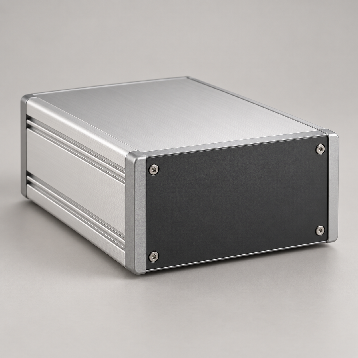
An extruded housing can form the body of a compact control unit. Board guides, connector access, panel attachment and mounting depend on the assembly drawing.
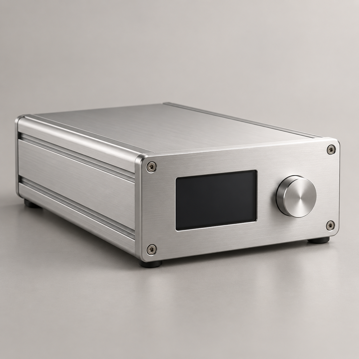
A profile housing can support a defined board and front-panel layout. Display openings, controls, internal clearance and finish should be specified for the actual unit.
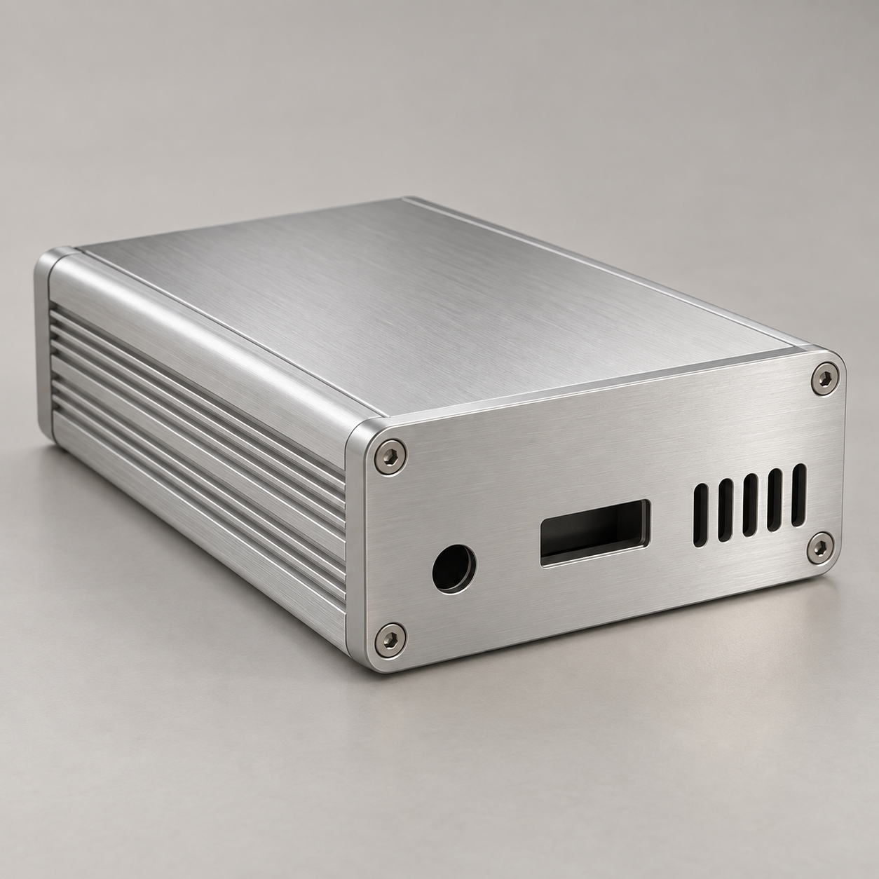
An enclosure profile may frame compact communications electronics. Connector placement, cable access, board retention and environmental needs require project-specific review.
A preliminary package can start the sourcing discussion. Keep unresolved fit, finishing and environmental questions visible for review.
Keep board fit, profile features and finished-part requirements connected as the inquiry is reviewed.
Send the profile drawing or sample reference together with the PCB envelope, cut length and supply details already known.
Mark unresolved clearances, end-panel interfaces, connector openings, material, finish and machining requirements.
Continue the sourcing conversation after the profile reference, supporting documents and remaining project questions have been reviewed.
These external pages illustrate enclosure details and general extrusion design topics. They do not verify products, services or capabilities from this site.
A commercial enclosure example showing internal PCB slots, sliding features and metal or plastic end-panel options.
A complete enclosure example that combines an extrusion, end panels, gaskets and hardware for a stated protection design.
A reference entry point for alloy selection, profile tolerances, surface treatment, fabrication and machining topics.
General answers to help prepare an aluminum extrusion profile requirement for electronic equipment.
Share a drawing or profile reference, PCB envelope and end-panel details. The inquiry can identify open dimensions and finished-part questions for the next sourcing discussion.
Your requirement will be used to coordinate the next sourcing step.