
Aluminum profiles for electronics housings
Enclosure Extrusion Profile
An Enclosure Extrusion Profile forms the aluminum body of an electronics housing. Aluminum Profile Works supplies standard and custom specifications for equipment manufacturers and B2B buyers. Check the PCB space and mating interfaces, work through a thickness-clearance example, and identify whether your requirement needs cutting, local machining or a different cross-section before requesting a quote.
Check the marked section dimensions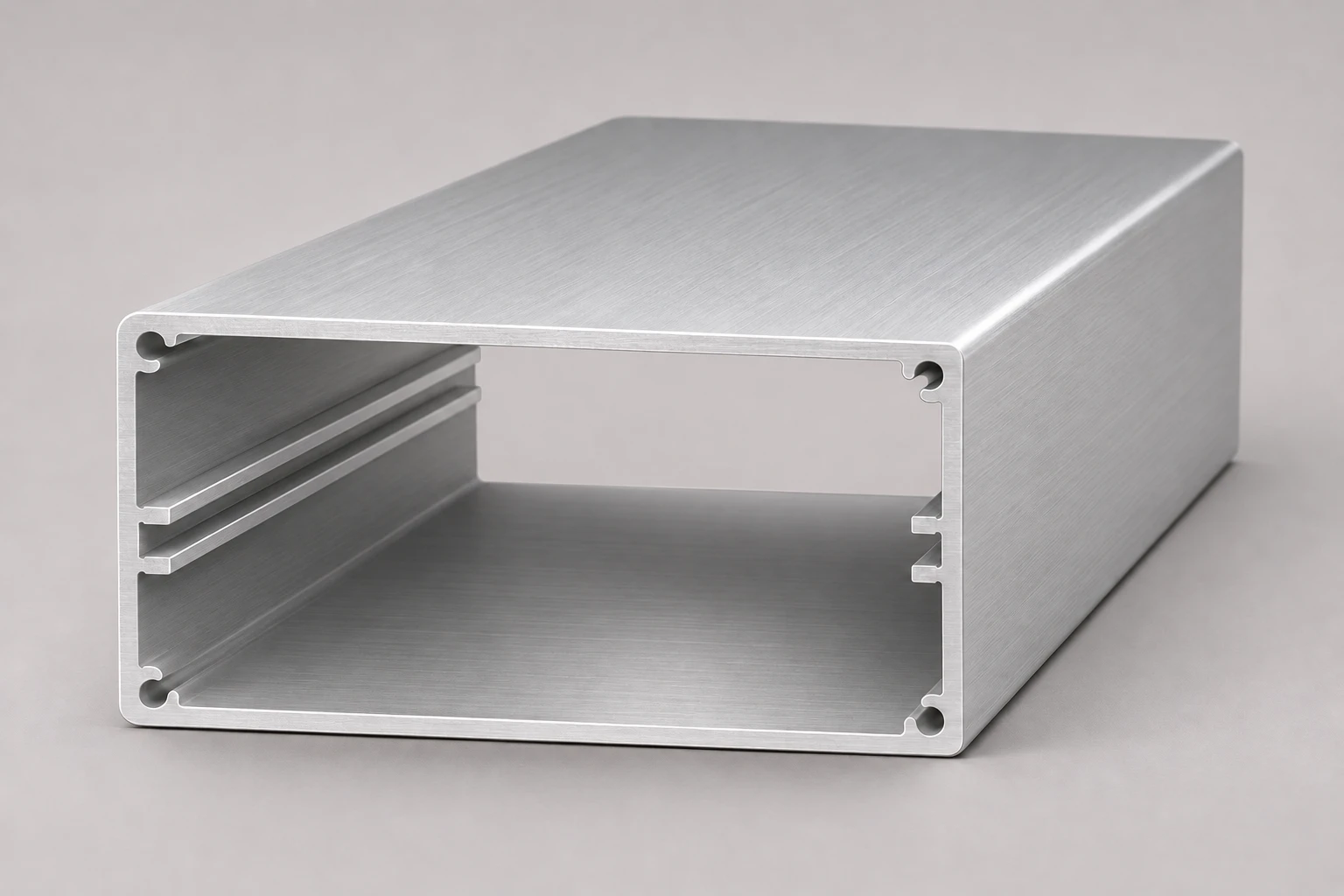
The open body reveals the guide ribs and corner channels, with the satin metal texture visible on the top and side.
Build the specification around the electronics
Select an Enclosure Extrusion Profile around board fit, assembly access and the finished supply condition. Hammond documents sliding PCB guides and end panels in its enclosure designs; their geometry needs to work with the board and mating parts. [1]
Check the board before selecting the body
Use the marked cavity and guide dimensions to identify thickness, component-space and insertion requirements. The outside envelope alone does not establish usable PCB space.
Choose the appropriate supply route
Separate finished-length changes and local holes from changes to the continuous section. AEC describes functionality integrated into extrusion designs; discrete windows and holes need separate fabrication requirements. [3]
Define the parts you need quoted
Identify the profile body, end panels, seals, screws and any mounting accessories separately. Include material, final surface condition and inspection requirements in the request.
Enclosure Extrusion Profile product information
- Profile category
- Enclosure Extrusion Profiles
- Product family
- Aluminum electronics enclosure bodies
- Section specification
- Standard and custom sections; define internal clearance, PCB guides, end-panel interfaces and finished length by drawing
- Supply specification
- Define the applicable product standard, material and tolerances on the order drawing
Match your changes to a supply route
For an Enclosure Extrusion Profile, changing finished length, adding local openings and changing continuous geometry are different requests. Compare the three routes, then provide the drawings needed to review the selected specification.
| Requirement | Existing section, cut to length | Existing section, locally machined | Custom continuous section |
|---|---|---|---|
| What changes | Finished length; the section remains the same | Holes, connector windows or other specified local features | Cavity width or height, guide positions, walls or continuous channels |
| Drawing to provide | Existing section reference, finished lengths and end requirements | Section reference plus a dimensioned machining drawing with datums | Required cross-section plus mating-part and finished-part drawings |
| Interfaces to check | PCB fit, existing guides and end-panel connection | All existing fits plus access, opening positions and remaining material | Board envelope, guide geometry, covers, end panels and fasteners |
| Confirm in the quotation | Section and tooling availability, cut tolerances and quantities by length | Machining feasibility, final surface sequence, tolerances and supply scope | Section feasibility, tooling, samples and critical-fit inspection |
These routes describe requirements, not confirmed stock or machining capability. Material, finish, operations, tooling, minimum order, price and lead time are confirmed for the actual request.
Enclosure Extrusion Profile dimensions to check
Match A–I to the cross-section and length views. For an Enclosure Extrusion Profile, identify each measurement plane, datum and finished surface condition on the drawing. Cavity measurements and guide geometry must be reviewed together with the complete insertion path.
- Outside width
- Measure between the specified external faces. Include any projecting feature in the equipment envelope and state whether the dimension applies after finishing.
- Outside height
- Dimension the overall section height from its datum. Check the installation envelope and any mounting or cover projection separately.
- Internal cavity width
- Identify the measurement plane between the inner walls. Guide ribs, corner features, fasteners and connectors may reduce usable space elsewhere along the insertion path.
- Internal cavity height
- Dimension internal height and locate the PCB within it. Check component heights on both board faces; total cavity height is not clearance above the board.
- PCB guide opening
- Specify the opening between opposing groove faces, including its limits in the finished surface condition. Compare the minimum opening with maximum PCB thickness.
- PCB guide depth
- Dimension the retaining depth on each side. Review it with board width, spacing between the guides, board-edge exclusions and the required insertion clearance.
- Guide position from a datum
- Locate the guide reference plane from the specified inner-floor datum. State the reference plane explicitly and check that both guides align with the board and connectors.
- End-panel attachment interface
- H identifies a corner connection feature, not a universal screw size. Define the mating panel, channel or hole geometry, fastener and engagement requirements on the assembly drawing.
- Finished body length
- Measure between the specified end faces. Check PCB length, connector projection, panel intrusion and assembly access; body length alone does not establish usable internal length.
Work through a PCB thickness-clearance check
Use this Enclosure Extrusion Profile example to understand one thickness-direction check. Calculate the maximum board thickness first, then subtract it from the minimum finished guide opening. Agree critical characteristics and tolerances with the supplier. [5]
- Assume PCB thickness is specified as 1.60 ± 0.15 mm.
- Assume the minimum guide opening is 1.90 mm after surface treatment, with its manufacturing tolerance already accounted for.
- All values are in millimetres. These example inputs are not APW supply dimensions or recommended universal fit allowances.
Maximum PCB thickness = nominal PCB thickness + positive thickness tolerance Minimum total thickness clearance = minimum finished guide opening − maximum PCB thickness
Maximum PCB thickness = 1.60 + 0.15 = 1.75 mm Minimum total thickness clearance = 1.90 − 1.75 = 0.15 mm
| Thickness-check quantity | Example value |
|---|---|
| Nominal PCB thickness | 1.60 mm |
| PCB thickness tolerance | ±0.15 mm |
| Maximum PCB thickness | 1.75 mm |
| Minimum finished guide opening | 1.90 mm |
| Minimum total thickness clearance | 0.15 mm |
The 0.15 mm result is total clearance across the thickness direction, not clearance on each face. It is not an assembly acceptance limit or proof that the board will slide into place.
A positive thickness clearance does not establish complete Enclosure Extrusion Profile compatibility. Check guide position and parallelism, entrance burrs, board bow and component interference through the full insertion path. Because the opening here is already a minimum finished dimension, do not subtract the same finishing allowance again.
Discuss your board and guide-fit requirementsFind the first checks for an assembly problem
Use the Enclosure Extrusion Profile symptoms below to organize an investigation. The causes are possibilities, not a diagnosis; compare measured parts, the approved drawing and mating components in the same finished condition.
| Observed symptom | Possible contributors | First checks |
|---|---|---|
| The PCB stops at the entrance | Board thickness and guide opening mismatch, entrance burrs or an obstructed board edge | Measure maximum board thickness and minimum finished opening; inspect the cut end and PCB edge |
| The PCB starts but jams farther in | Guide position or straightness variation, board bow, or component and fastener interference | Check the full guide path and board envelope; locate where contact starts before changing dimensions |
| The end panel will not seat | PCB, connector or fastener intrusion into the end space, or a mismatched panel interface | Check usable internal length, connector projection, end-face condition and panel mating geometry |
| The fit becomes tight after finishing | Build on a mating surface, or dimensions checked in different surface conditions | Measure finished groove and mating-part dimensions against the approved drawing; confirm treatment and any specified masking |
Record the drawing revision, surface condition, measured location and affected mating parts. Review changes with the supplier rather than treating one measured part as a new production tolerance.
Geometry and surface details
Enclosure Extrusion Profile product views
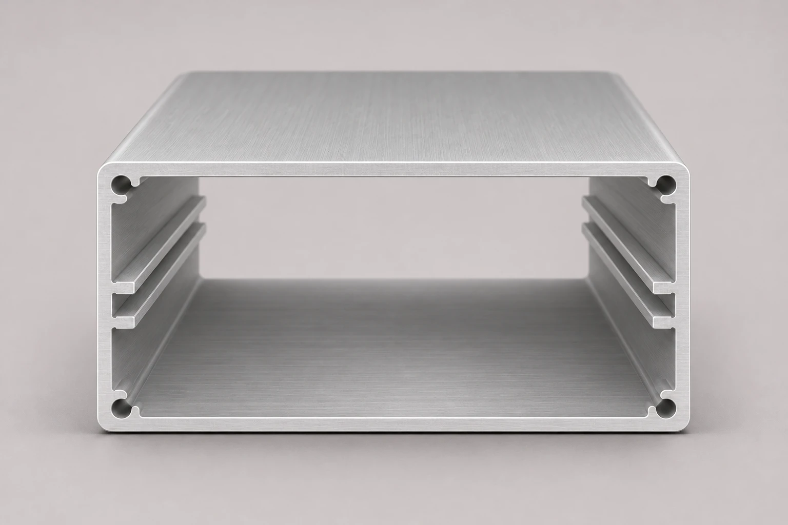
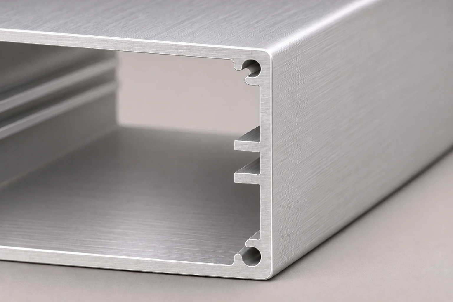
These views show the body geometry and visible surface. Confirm the selected section, dimensions and finished condition on the order drawing.
Electronics housing requirements to discuss
Match the Enclosure Extrusion Profile to the equipment layout and operating conditions. These application questions help define a drawing; they do not establish a tested rating for the profile.
- Industrial controllers
Locate the control board, terminal access and mounting interface. Check whether connectors can pass through the end-panel openings during assembly.
- Measurement instruments
Define display access, front-panel controls, board retention and service access. Identify visible surfaces and cosmetic acceptance requirements.
- Electronic interface modules
State the board envelope, connector orientation and cable space. If heat dissipation matters, provide the thermal requirements for separate engineering assessment.
Specify the finished part, not just the raw section
Your Enclosure Extrusion Profile RFQ should state alloy and temper when required, finished lengths, quantity, surface treatment and any machining. Locate holes and windows from drawing datums, identify cosmetic faces and define whether dimensions apply before or after finishing. Ask for any required material or inspection documents in the quotation.
Review end panels, fasteners and sealing together
Treat the Enclosure Extrusion Profile as one component of the housing. Hammond's sealed enclosure series combines an extruded body with end panels, gaskets and assembly hardware; those assembly details are separate from the body geometry. [2]
Attachment details
Specify screw type, engagement requirements and mating-hole locations. Do not select assembly torque from the extrusion outline alone; use the approved joint specification.
Seals and conductive interfaces
If required, define seal seats, cable entries and electrical contact areas in the assembly drawing. State the target ingress and EMC requirements for the completed equipment, rather than assuming the bare extrusion meets them.
Prepare a profile RFQ
Use this Enclosure Extrusion Profile checklist to organize the information for your quotation. Fill in the project requirements and mark unresolved items for review.
- Section reference
- Existing profile reference or cross-section drawing with revision and units
- Board and assembly
- PCB envelope, thickness limits, component clearance, guide locations and mating-part drawings
- Material and surface
- Required alloy, temper, finish, cosmetic faces and any contact-area masking requirements
- Length and processing
- Finished lengths, cut tolerances, end condition, hole patterns and connector windows
- Supply boundary
- Profile body only, or a separate request for end panels, seals, fasteners and other parts
- Order and inspection
- Quantity by length, sample requirements, critical checks, requested documents and delivery destination
The checklist defines a quotation request, not a fixed catalog configuration. Identify missing dimensions and ask for confirmation of the selected material, operations, tooling and supply scope.
Send your profile requirementsAgree the sample checks before production
Evaluate the Enclosure Extrusion Profile sample in its specified finished surface condition, using the approved drawing revision and designated mating parts. Record the agreed critical dimensions and acceptance limits before production. [5]
Measure guides and verify full PCB insertion
Measure finished guide openings and positions at the drawing-defined locations. Use the designated PCB or an agreed representative assembly to check the complete insertion and removal path. Record contact or interference; use the approved drawing for dimensional limits.
Assemble end panels and inspect openings
Check body length, end condition and machined-feature positions from the specified datums. Fit the designated panels, fasteners and connectors, then verify seating and access against the assembly drawing.
Inspect finished surfaces and retain records
Inspect the agreed cosmetic faces and any specified contact-area masking in the final surface condition. Retain measured results and requested material or treatment records. Assess specified ingress or EMC performance separately on the completed assembly.
Enclosure design references
The numbered sources support the design explanations. Manufacturer examples describe their own products and do not define APW dimensions, included parts or performance.
- [1] Hammond 1455: PCB guides and enclosure componentsDocuments sliding PCB installation, removable plates on selected models and end-panel options.
- [2] Hammond 1457: sealed enclosure constructionShows the body, end panels, gaskets and hardware used together in a documented sealed enclosure series.
- [3] AEC: aluminum extrusion design resourcesGuidance covering extrusion functionality, alloys, tooling, tolerances, fabrication and thermal management.
- [4] IEC 60529: degrees of protectionDefines the scope of the IP Code classification for protection provided by electrical equipment enclosures.
- [5] AEC: extrusion tolerancesExplains standard and precision tolerance considerations and the need to discuss component-specific requirements with the extruder.
Enclosure Extrusion Profile questions
Is the profile supplied as a complete enclosure?
An Enclosure Extrusion Profile is the extruded body section. End panels, seals, screws and mounting accessories are separate items unless explicitly included in the quotation. State the required supply boundary and provide mating-part requirements.
Can I change the Enclosure Extrusion Profile length or cross-section?
Yes. APW supplies standard and custom specifications. A length change retains the selected cross-section; moving guides or changing the cavity changes the section requirement. Send the reference drawing, required finished lengths and quantities so the appropriate supply route can be quoted.
How do I choose a profile for my PCB?
Check board width and thickness against the guide geometry, then check components on both board faces, connector projection and the full insertion path. Do not infer usable board space from outside width and height. Include board limits and critical fit requirements on the drawing.
Which alloy and surface treatments are available?
Request the required alloy, temper and treatment in the RFQ; these are confirmed for the selected specification. Define visible surfaces, coating requirements and any electrical contact areas. No single alloy or finish is assigned to every profile in this family.
Does an aluminum extrusion automatically provide an IP or EMC rating?
No. Do not infer an equipment rating from the bare profile. IEC 60529 covers degrees of protection provided by enclosures. End panels, seals, cable entries and assembly details must be addressed for a specified ingress requirement; EMC requirements also need assessment of the completed design. [2, 4]
What information is needed for a quotation?
Provide the profile reference or section drawing, PCB and mating-part details, material and finish requirements, finished lengths, processing, quantities and destination. List sample checks and required documents. Minimum order, tooling, availability, price and lead time are confirmed with the quotation.
Related aluminum profiles for thermal design
Turn your enclosure requirements into a clear RFQ
Choose an Enclosure Extrusion Profile by checking the cavity, guides and mating interfaces. Use the thickness-clearance method and assembly checks to define your requirement, then send the section reference, processing details and quantities for a standard or custom quotation.
Browse aluminum profiles