
Aluminum extrusions for electronic cooling
Finned Heat Sink Profile
A Finned Heat Sink Profile combines a continuous aluminum base with projecting fins to spread heat and expose more surface to the surrounding air. Aluminum Profile Works supplies standard and custom sections for power supplies, industrial electronics and lighting assemblies. Compare section dimensions below, then send your drawing, finished lengths, quantity and cooling conditions for a quote.
Check fin geometry and cooling requirements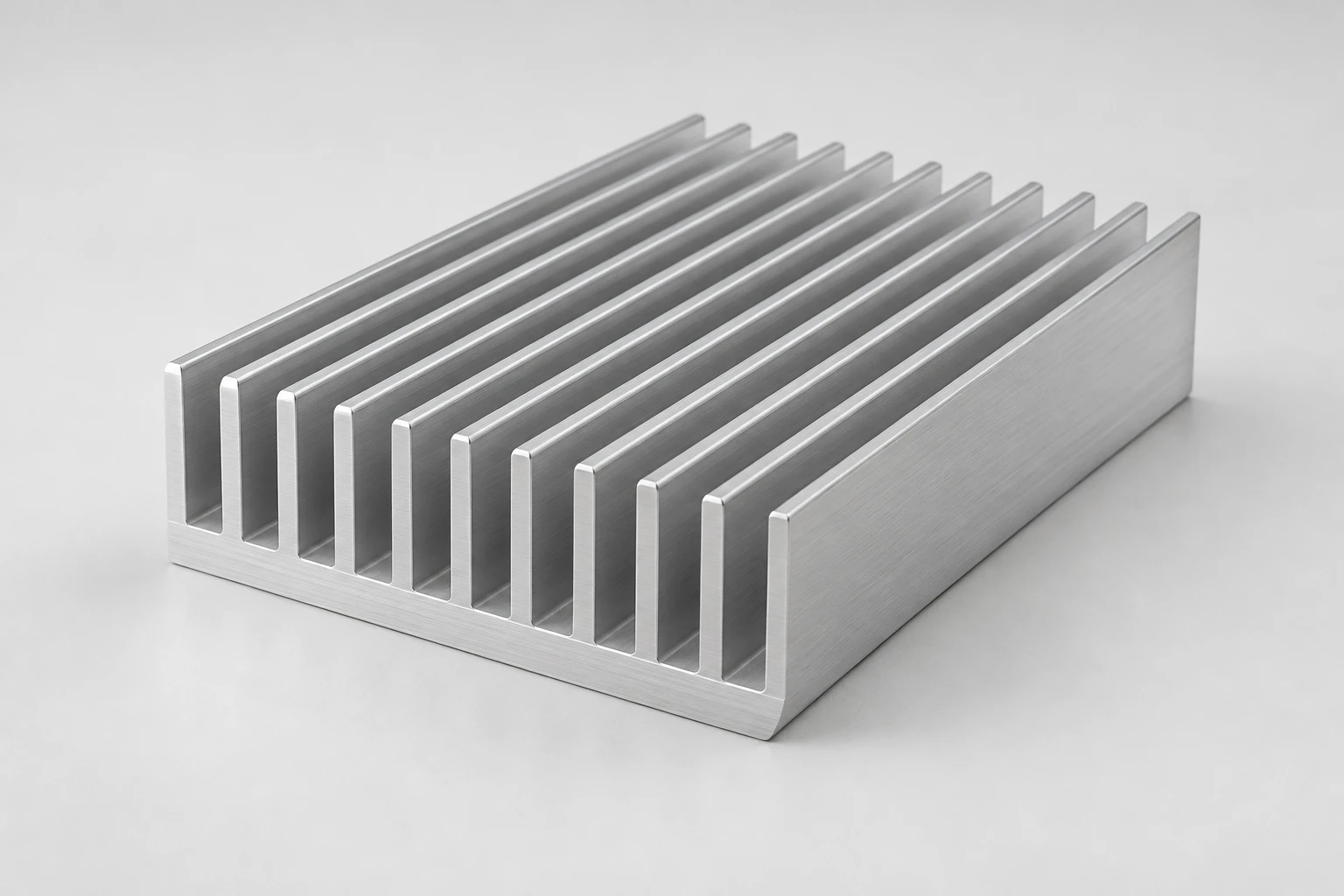
A continuous base supports straight fins along the extrusion length.
Specify the section around the heat source
Choose a Finned Heat Sink Profile by considering the mounting footprint, available space and airflow together. A useful specification connects the extruded shape to the finished assembly.
Continuous base and straight fins
The extruded base and fins form one section. Define the heat-source footprint and contact face so heat can spread into the finned area. [5]
Standard or custom cross-sections
Start from an existing section or a new drawing. Identify fixed mating dimensions and flexible features before reviewing the section and any tooling requirement.
Finished parts defined by drawing
Specify cut length, material, finish and mounting details. Keep the continuous extrusion separate from requested drilling, tapping or contact-face machining.
Finned Heat Sink Profile specifications
- Profile category
- Heat Sink Profiles
- Product family
- Straight-fin aluminum heat sink extrusions
- Section specification
- Standard and custom cross-sections; specify width, height, base, fins and finished length by drawing
- Supply specification
- Material, product standard, tolerances and finished condition agreed for the selected drawing
Compare four section sizes
Use these documented cross-sections to start a Finned Heat Sink Profile inquiry. Width, total height and base thickness are separate dimensions; finished length runs along the extrusion. Dimensions below are in millimeters. [1–4]
| Section dimension (mm) | 33 × 14 [1] | 100 × 40 [2] | 300 × 60 [3] | 320 × 20 [4] |
|---|---|---|---|---|
| Overall width | 33 | 100 | 300 | 320 |
| Total height, including base | 14 | 40 | 60 | 20 |
| Base thickness | 1.8 | 10 | 12 | 4 |
Other standard and custom sizes can be supplied against your requirements. The linked Fischer Elektronik data sheets establish the listed geometry, not an APW stock code or thermal rating. Confirm the complete section, finished length and supply specification in the quotation.
Read the heat sink cross-section
Specify a Finned Heat Sink Profile with eight distinct dimensions. The cross-section defines the base and fins; the length view shows the direction in which the extrusion is cut.
- Overall width — W
- Measure across the outside of the section, perpendicular to its extrusion length.
- Total height — H
- Measure from the bottom contact face to the fin tips. Total height includes the base.
- Base thickness — B
- Measure from the bottom contact face to the plane where the fin channels meet the base.
- Fin height — h
- Measure above the base to the fin tips. In the straight-fin section shown, h = H − B.
- Fin thickness — t
- Dimension the fin plate itself. For tapered fins, state the measurement position on the drawing.
- Clear fin gap — s
- Measure the open space between adjacent fins. For tapered fins, identify where the gap is measured.
- Fin pitch — p
- Measure between corresponding points on adjacent fins. For uniform, parallel fins, p = t + s.
- Finished length — L
- Measure along the extrusion direction. State the cut length and its tolerance separately from the cross-section.
Turn the temperature limit into a thermal target
Before choosing a Finned Heat Sink Profile, establish the required sink-to-ambient thermal resistance. This static example uses a bottom contact-face temperature limit, not a semiconductor junction-temperature limit. [5]
- Use a simplified steady-state heat path: all 40 W enters the heat sink and leaves it to the surrounding air.
- The 40 W value is heat dissipation, not automatically the electrical input power of the device.
- Use local ambient air temperature and evaluate the installed orientation, airflow and heat-source footprint.
Required Rθsa ≤ (Ts,max − Ta) ÷ Q
(80°C − 40°C) ÷ 40 W = 1.0°C/W Required Rθsa ≤ 1.0°C/W
| Design input or target | Example value | Meaning |
|---|---|---|
| Heat load — Q | 40 W | Heat entering the heat sink |
| Ambient air temperature — Ta | 40°C | Air surrounding or entering the heat sink |
| Allowed base temperature — Ts,max | 80°C | Maximum permitted temperature at the base contact area |
| Required sink-to-ambient resistance — Rθsa | ≤ 1.0°C/W | Target to verify for the intended cooling conditions |
The temperatures and heat load are example design inputs. The result is a selection requirement, not a measured thermal rating of any listed section.
A Finned Heat Sink Profile meets the target only when its performance is established under matching conditions. If the limit comes from semiconductor junction temperature, account for junction-to-case and case-to-sink resistance before selecting the sink. [5]
Send your drawing and thermal requirementsCheck the heat path when temperatures are too high
Use these checks to investigate a Finned Heat Sink Profile installation. A temperature pattern suggests checks; it does not identify a cause by itself. [5]
| Observed condition | Possible contributors | First checks |
|---|---|---|
| Device is hot; heat sink remains relatively cool | Contact-interface resistance, uneven mounting or different measurement locations | Check the mating surfaces, interface material and mounting method; compare temperatures at defined locations. |
| Acceptable in open air; hotter inside the enclosure | Restricted airflow, recirculated warm air or nearby heat sources | Check inlet and outlet paths, fin clearance and local air temperature with the enclosure assembled. |
| Adding fins brings little improvement | Restricted channel flow or a different bottleneck in the heat path | Review clear fin gaps, installed orientation and actual channel airflow before increasing fin density. |
| Changing material brings little improvement | Contact or air-side resistance dominates the thermal path | Compare the interface and airflow under the same conditions; do not assume alloy conductivity is the limiting factor. |
Compare the same operating load, ambient conditions, cooling arrangement and measurement locations. Confirm the cause with measurements before changing the part.
Base, channels and cut-face details
Finned aluminum profile views
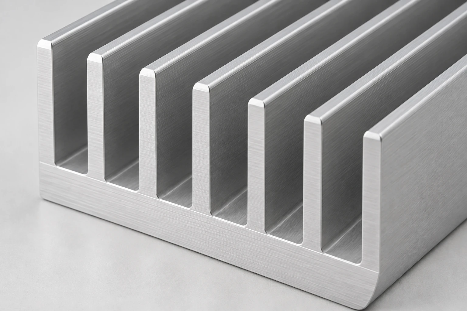
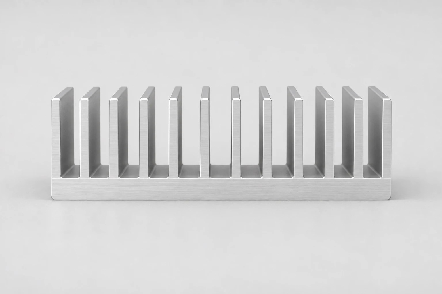
Use the approved drawing to define dimensions, tolerances and the ordered surface condition.
Choose fin geometry for the airflow
Fin spacing in a Finned Heat Sink Profile must suit the installed airflow. Record these operating conditions alongside the dimensioned drawing. [5]
- For natural convection, describe the installed orientation, clearances and unobstructed path for rising warm air.
- For forced-air cooling, specify airflow through the fin channels and the fan operating conditions, including enclosure restrictions.
- Provide heat load, maximum ambient temperature and the relevant component or contact-face temperature limit.
- Use the eight dimension definitions above to identify fixed dimensions and available space.
- Identify the heat-source footprint, contact-face flatness, fasteners and thermal interface material.
- Evaluate the assembled device with its actual heat source, interface, orientation and cooling arrangement.
Match the cooling section to the assembly
Define the interfaces and operating environment for each application before selecting the section.
- Power supplies and converters
Locate the power devices on the base and show fastener access, electrical isolation requirements and airflow around surrounding components.
- Industrial electronic assemblies
Provide enclosure clearances, mounting orientation and duty cycle. Identify blocked channels or nearby heat sources that affect the installed cooling path.
- Lighting modules
Show the board footprint, contact interface and ventilation path. For lighting-specific board and luminaire considerations, see the related LED profile page.
Turn the cross-section into an order requirement
For a Finned Heat Sink Profile quote, send the section and finished-part drawings with their revision, quantity and destination. Use the example below to organize material, finish, machining and acceptance requirements. Price, tooling, minimum order quantity and lead time are confirmed for the selected requirement.
Check these details before selecting a profile
Separate the geometry that controls fit from the conditions that control heat transfer.
Base and mounting footprint
Base thickness and heat-source position affect heat spreading. Specify the contact area and available mounting space rather than selecting thickness by appearance. [5]
Drawing and installed airflow
Mark fixed mating dimensions and the direction of airflow through the installed section. Include restrictions imposed by the enclosure. [5]
Material and finished surface
6063 and 6061 are used for aluminum heat sink extrusions. Specify the required alloy, temper and finish for your part; no single combination defines this product family. [6]
Standard versus custom
For a standard section, verify the complete drawing. For a custom section, mark fixed dimensions and request tooling review. Both routes need a finished-part specification.
Example inquiry: section, length and cooling conditions
This Finned Heat Sink Profile RFQ example shows how to organize a requirement. Replace the example entries with your assembly data.
- Cross-section
- 100 mm wide × 40 mm total height, 10 mm base; attach the complete fin geometry and drawing revision
- Finished length and quantity
- 150 mm cut length; 200 pieces
- Material and finish
- State required alloy, temper and finish, including any contact-face masking
- Mounting features
- Attach hole and thread locations, contact footprint, flatness requirement and inspection datums
- Thermal conditions
- State heat load, ambient temperature, temperature target, interface material, orientation and airflow
- Supply and acceptance
- State destination, requested schedule, critical tolerances and agreed inspection conditions
The example length and quantity are inquiry inputs, not stock availability or minimum order terms. The drawing defines the complete part; the envelope alone does not specify the fins.
Discuss your profile drawingAgree inspection and thermal evaluation
Use the approved drawing and intended operating conditions as the acceptance basis.
Geometry and fit
Inspect section dimensions, finished length, straightness, mounting features and edge condition against the agreed drawing revision.
Contact face and finish
Confirm contact-face condition, finish and masking requirements using the specified inspection method.
Assembly temperatures
Record load, ambient conditions, airflow and interface configuration when assessing measured temperatures against the agreed target. [5]
Section data and thermal design resources
The section sheets support the geometric comparison; the engineering guides explain selection principles.
- [1] Fischer Elektronik: SK 636 section33 mm width, 14 mm total height and 1.8 mm base thickness.
- [2] Fischer Elektronik: SK 92 section100 mm width, 40 mm total height and 10 mm base thickness.
- [3] Fischer Elektronik: SK 568 section300 mm width, 60 mm total height and 12 mm base thickness.
- [4] Fischer Elektronik: SK 579 section320 mm width, 20 mm total height and 4 mm base thickness.
- [5] Boyd: How to Select a Heat SinkThermal resistance, airflow and the relationship between fin spacing and fin length.
- [6] Boyd: Heat Sink Fabrications GuideExtruded aluminum construction, material choices and fabrication comparisons.
Finned heat sink selection questions
Do denser fins always improve cooling?
No. A Finned Heat Sink Profile needs airflow between its fins. Increasing fin density adds surface but can restrict the flow that removes heat. Select spacing for natural convection or the actual forced-air conditions, then evaluate the assembly. [5]
Can the outside dimensions determine thermal resistance?
No. Thermal resistance also depends on fin geometry, finished length, orientation, airflow and the measurement conditions. Two parts with the same width and height can perform differently. The size table is a geometric comparison, not an APW thermal rating. [5]
Which aluminum alloy should I specify?
6063 and 6061 are used in extruded heat sinks. Select alloy and temper alongside the section design, mechanical requirements and finish. Include the requirement in your inquiry and confirm it for the ordered part. [6]
Can I request cutting and mounting features?
Yes. Include finished lengths, hole positions, threads and contact-face requirements on the drawing for quotation review. Requested secondary operations must be confirmed for the finished part; they are not defined by the continuous cross-section.
Are other section sizes and custom fins available?
Standard and custom specifications can be supplied. Send the complete cross-section and identify fixed dimensions, fin spacing and mounting interfaces. The four listed sizes are starting points, not the limits of the product range.
What should a custom profile inquiry include?
Provide the section drawing, finished-part details, material and finish requirements, lengths, quantity and destination. Add heat load, ambient conditions, temperature target, orientation and airflow so fit and cooling requirements can be considered together.
Related heat sink profile
Bring the section and cooling requirements together
Specify your Finned Heat Sink Profile with a complete drawing, finished lengths and operating conditions. Send the requirement and quantity to discuss a standard section or custom extrusion.
Browse aluminum profiles