
Aluminum profiles for PV mounting assemblies
Solar Mounting Rail
A Solar Mounting Rail supports photovoltaic modules and connects their clamps to the mounting structure. Aluminum Profile Works supplies aluminum rail profiles in standard and custom specifications for B2B buyers. Compare reference sections, define the mating interfaces and send your drawing, material, finish, finished length and quantity for a quote.
Check the rail interfaces before quoting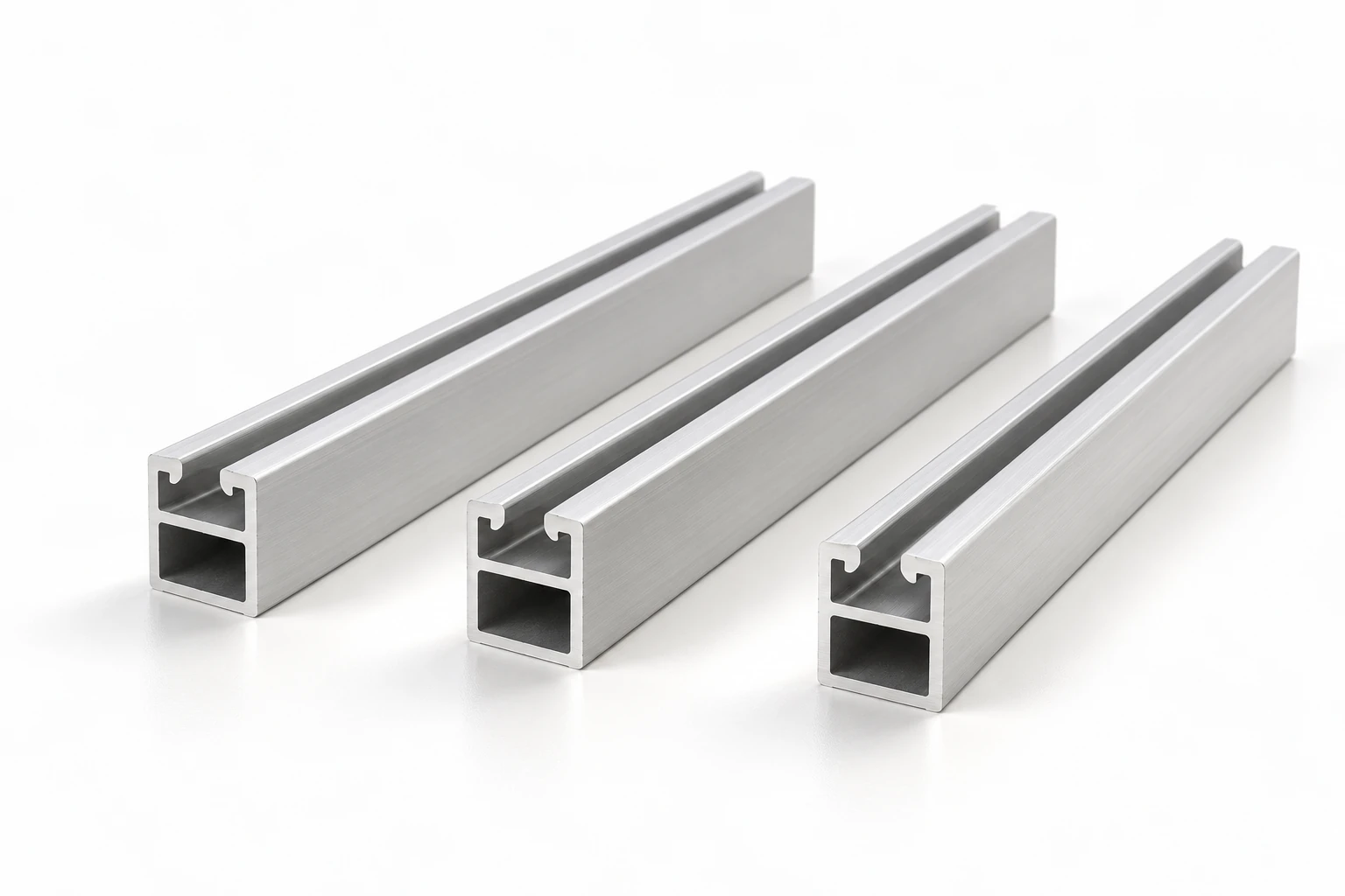
The upper clamp channel and enclosed lower cavity continue along each rail sample.
Specify the section around the mounting assembly
A Solar Mounting Rail combines continuous extrusion features with the connections required by the selected system. Rail geometry, clamps, splices and attachments must be reviewed together. IronRidge documents different rail sections and project-dependent span requirements within its own system. [4]
Standard and custom sections
Choose a reference envelope or submit a dimensioned section. Include the internal geometry and critical fits so the quotation covers the complete profile rather than just its width and height.
Defined clamp and splice interfaces
Identify the clamp-channel opening, retaining surfaces and connector cavity. Provide mating-component drawings to distinguish a geometric match from a similar-looking extrusion.
An explicit finished supply condition
Specify material, finish, finished lengths, end preparation and inspection requirements together. State any hole pattern or machining operation separately from the continuous extruded section.
Solar Mounting Rail product information
- Profile category
- Solar Mounting Rails
- Product family
- PV module support rail extrusions
- Section specification
- Standard and custom sections; specify clamp channel, splice cavity, support interface and finished length by drawing
- Supply specification
- Specify the applicable product standard, material and tolerances on the order drawing
Solar Mounting Rail reference sizes
Compare three documented manufacturer references by overall width and height. These discrete sections help frame a size inquiry; they do not define a continuous size range or interchangeable hardware. Each column links to its K2 Systems source. [1–3]
| Published reference parameter | K2 SingleRail 36 | K2 SingleRail 50 | K2 SingleRail 63 |
|---|---|---|---|
| Overall width × height (mm) | 39.4 × 36 | 39 × 50 | 47 × 63 |
| Length of linked reference (m) | 4.80 | 4.80 | 6.10 |
| Source alloy and temper | EN AW-6063 T66 | EN AW-6063 T66 | EN AW-6063 T66 |
| Source surface condition | Mill finish | Mill finish | Mill finish |
| Connection described by source | Side connection | Side connection | Side connection |
APW supplies standard and custom specifications against the agreed order drawing. K2 names identify the source products, not APW model names or a claim to supply original K2 components. Source approvals, load tables and accessory compatibility apply to the identified manufacturer's system; they do not transfer to another extrusion.
Solar Mounting Rail Interface Checks
Check a Solar Mounting Rail against the mating parts as well as its outside dimensions. Use A–G to locate the features that need dimensioning on your section drawing.
- Overall width
- Measure the complete outside width. Provide the available assembly envelope and the selected section drawing with units and revision.
- Overall height
- Dimension the complete outside height from an identified datum. Show how the rail sits against the support and module-clamp assembly.
- Slot opening
- Dimension the clear opening between the retaining lips. Include the mating bolt or nut reference and its intended insertion orientation.
- Internal channel engagement width
- Show the internal width, seating depth and retaining surfaces. Supply the nut and clamp details needed to check engagement after finishing.
- Splice cavity
- Dimension the cavity envelope and internal corner geometry. Include the splice-connector drawing, insertion detail and required mating fit.
- Wall thickness
- Dimension each critical wall rather than assuming a uniform thickness. Identify the surfaces used for measurement and the specified finishing condition.
- Support connection face
- Identify the selected attachment face, contact area and hardware path. Provide the foot, bracket or support drawing, including any hole-position datums.
Solar Mounting Rail Cut-Length and Quantity Example
Turn a Solar Mounting Rail cut list into comparable piece and metre quantities. This worked order starts from two specified finished lengths; it does not calculate how many rails a module layout needs.
- Lengths are finished-part requirements with agreed end-face datums, not raw-stock lengths or a stock offer.
- The piece counts are supplied order inputs. Module layout, support spacing, rail splices and installation quantities require separate project design.
| Cut group | Finished length (mm) | Pieces | Finished net length (m) |
|---|---|---|---|
| A | 4,200 | 100 | 420 |
| B | 2,100 | 60 | 126 |
The order totals 160 pieces and 546 m of finished net length. Raw-material purchasing must separately account for stock lengths, saw kerf, end trimming and usable offcuts. Do not apply a default waste percentage or infer raw-stock quantity from the net total alone.
Finished net length (m) = Σ [finished length (mm) × pieces] ÷ 1,000. Group A: 4,200 × 100 ÷ 1,000 = 420 m. Group B: 2,100 × 60 ÷ 1,000 = 126 m. Total: 100 + 60 = 160 pieces; 420 + 126 = 546 m.
Send your cut list and quantitiesSolar Mounting Rail Fit-Up Troubleshooting
Use an observed fit-up problem to organize measurements and drawing feedback. These are possible checks, not a unique diagnosis or instructions to alter a rail or fitting.
| Observed problem | Possible contributors to check | Measurements and information to provide |
|---|---|---|
| Nut will not enter or seat in the channel | Slot opening, internal seating geometry, burrs, finishing condition or insertion orientation | Measure the opening and seating surfaces; provide the nut reference, section revision and photographs of its intended insertion position. |
| Splice connector is difficult to insert | Cavity and connector dimensions, internal corners, end burrs or dimensions after finishing | Provide cavity and connector measurements, their drawing revisions, surface condition and end-view photographs. |
| Joined rails do not align | Section revisions, connector fit, end-face condition or rail straightness against the specified datum | Record where the offset occurs, the mating sections and connector references; include end-face photographs and measurements against the drawing datums. |
| Clamp will not seat or contact the module frame correctly | Clamp or nut reference, assembly orientation, seating geometry or mismatch with the module-frame interface | Provide the clamp assembly reference, module-frame drawing and photographs showing the actual contact and seating positions. |
| Connection holes do not line up | Drawing revision, datum selection, hole coordinates, cut-length reference or component orientation | Compare specified and measured hole positions from the same datum; provide part revisions and a photograph of the intended connection. |
Compare the findings with the approved rail, fitting and assembly drawings before agreeing a corrective action. Include the affected part and lot references in the feedback.
Profile geometry and surface details
Solar Mounting Rail product views
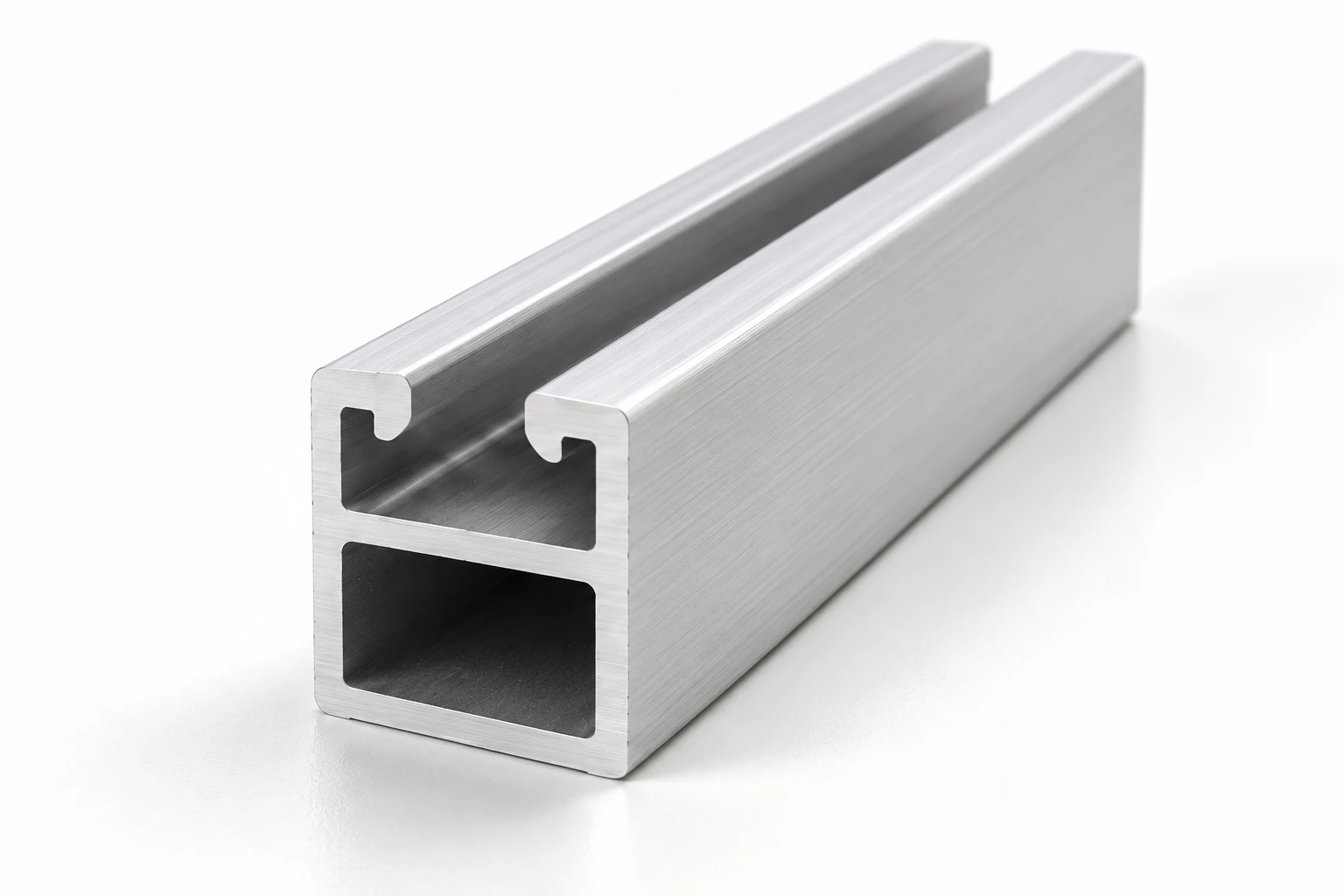
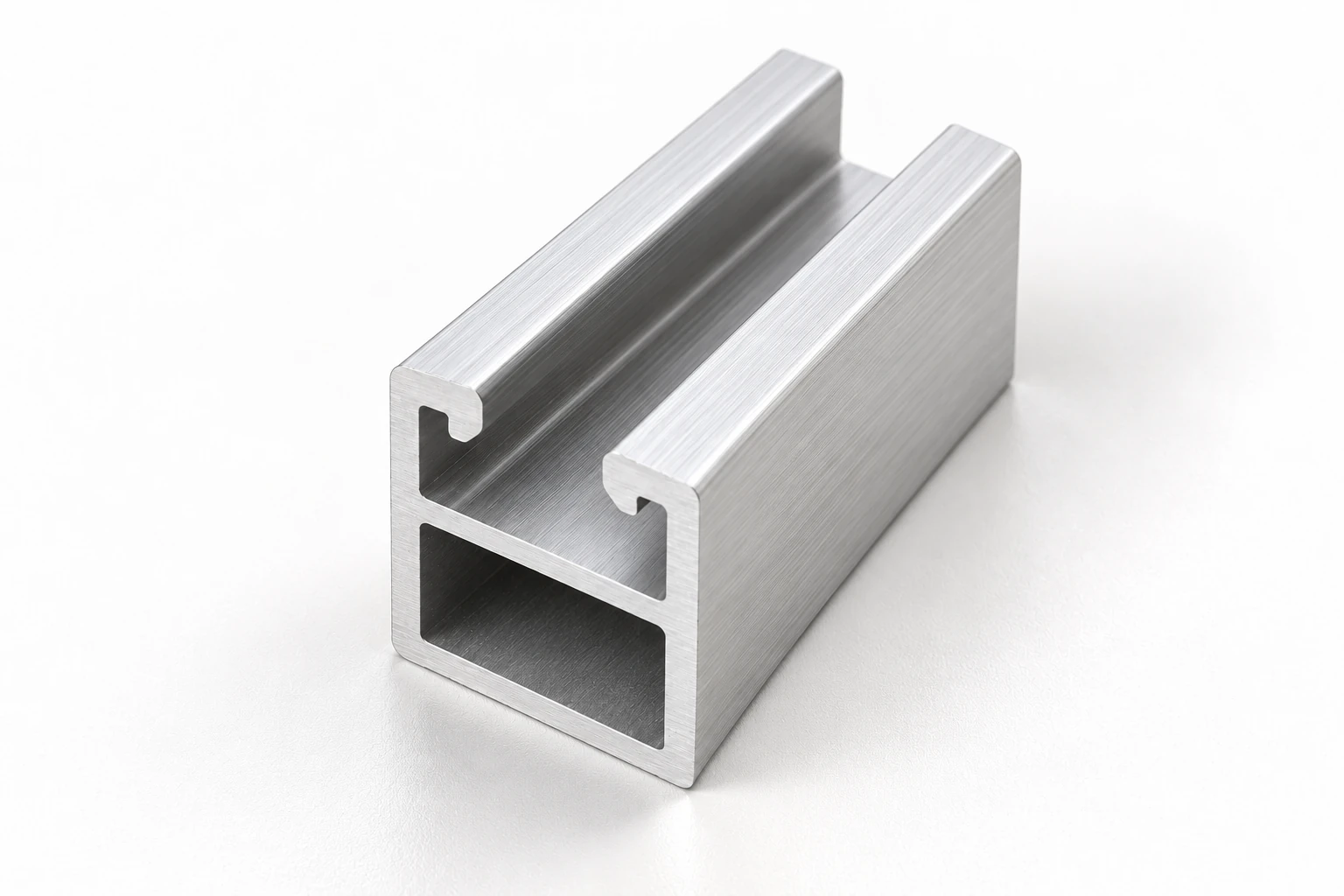
These views show one rail form. Confirm the selected cross-section, mating interfaces and supply specification on the order drawing.
Choose the geometry before the overall rail size
Use the interface checks above to define the section, then complete the material and finished-supply requirements below.
- Clamp channel: opening, internal engagement, bolt or nut retention and module-frame contact
- Splice cavity: connector envelope, engagement surfaces, joint detail and required fit after finishing
- Support connection: attachment face, bolt path, hole pattern and orientation in the assembly
- Material: specified alloy, temper, applicable product standard and required material records
- Surface condition: mill or treated finish, appearance requirements and dimensions after treatment
- Finished supply: cut lengths, end preparation, machining, inspection, quantity and packing
Rail interfaces in roof and ground-mount assemblies
A Solar Mounting Rail forms one part of the module-support assembly. Select the profile against the connections and engineering requirements of the actual project.
- Pitched-roof arrays
Coordinate the module-clamp channel with the selected roof hook, foot or other attachment. Roof construction and weatherproofing remain part of the complete roof-attachment design.
- Flat-roof arrays
Define how the rail connects to tilted supports or the selected mounting frame. Roof loading, restraint and attachment requirements depend on the approved system design.
- Fixed-tilt ground arrays
Match the rail-to-frame connection and splice arrangement to the support structure. Include project drawings rather than applying a roof-system span table to a ground-mounted assembly.
Prepare a Solar Mounting Rail supply specification
State whether you need finished rails or extruded lengths for further processing. Keep clamps, connectors and attachments as separate bill-of-materials items. Add material, finish, machining, inspection, packing and destination requirements to the cut list so price and delivery terms can be agreed for the actual order.
Identify the rail from a drawing or sample
Start with a cross-section drawing and mating references. For a replacement profile, a photograph helps identify the form but does not establish its dimensions or compatibility.
Record the section and revision
Show width, height, walls, channel opening and internal cavities with units and drawing revision. Identify the features that control assembly fit.
Define finished-part details
Add cut-length datums, end preparation and hole coordinates. State whether dimensions apply before or after finishing, and identify any reference sample.
Check the clamp, splice and support interfaces
Review the rail profile with its mating components. Similar profile dimensions do not establish system compatibility.
Clamps and module frames
Check bolt or nut engagement, retaining geometry, clamp contact and the module manufacturer's mounting requirements. Provide the actual component references.
Splices and movement provisions
Specify connector fit and joint requirements from the selected system documentation. Thermal movement and electrical bonding need their own defined details. [4–5]
Rail-to-support attachments
Check the fixing face, hardware seating and connection orientation against the approved support drawing. Keep installation torque requirements with the selected system instructions.
Loads and allowable spans
Use project-specific engineering and the applicable system documents for support spacing, cantilevers and site loads. Overall section height alone is not a load rating. [4]
Solar Mounting Rail RFQ checklist
Organize the information below into a single inquiry package. Mark open design decisions so the quotation does not silently assume an interface or material.
- Section and drawing
- Dimensioned cross-section, units, drawing number and revision; selected reference size or custom geometry
- Mating components
- Module clamp, bolt or nut, splice connector and rail-to-support drawings or part references
- Finished specification
- Alloy and temper, product standard, finish, finished lengths, tolerances and end preparation
- Processing and inspection
- Required hole patterns or machining; material records, dimensional checks and acceptance criteria
- Order and delivery
- Piece quantities by finished length, packing requirements, destination and requested delivery schedule
Supply drawings define the extrusion and finished part. Project engineering must separately establish the mounting-system loads, connections, movement provisions and bonding requirements.
Send your rail drawing and quantitiesAgree the receiving checks before ordering
Make the receiving criteria part of the order specification. Select checks relevant to the supplied condition.
Dimensions and fit
Agree measurements for critical channels, splice cavities, walls, finished lengths and any straightness or twist requirements. Define mating-fit checks where needed.
Finish and end condition
Define the required surface condition, appearance criteria, burr limits and protection of cut ends or contact surfaces. Inspect in the agreed finishing condition.
Material and traceability
Identify the material documentation required by the order, including alloy, temper and lot references. A reference product page is not a batch certificate.
Quantity and packing
Check quantities by length and drawing revision, bundle identification and transport protection. Keep packing marks consistent with the purchase documents.
Technical sources for section and system requirements
The numbered sources support the reference dimensions and system considerations above. Manufacturer-specific dimensions and approvals retain their original scope.
- [1] K2 SingleRail 36 — 2004393Manufacturer reference for a 39.4 × 36 mm rail, linked 4.80 m length, EN AW-6063 T66 material and mill surface.
- [2] K2 SingleRail 50 — 2004414Manufacturer reference for a 39 × 50 mm rail, 4.80 m length, EN AW-6063 T66 material and mill surface.
- [3] K2 SingleRail 63 — 2001851Manufacturer reference for a 47 × 63 mm rail, 6.10 m length, EN AW-6063 T66 material and mill surface.
- [4] IronRidge XR rail documentationRail-family documentation with section options, splices and project-dependent span criteria for the identified IronRidge systems.
- [5] UL 2703 standard scopeScope of evaluation for PV mounting, retention and grounding or bonding components and identified module combinations where applicable.
Solar Mounting Rail purchasing questions
What does a Solar Mounting Rail do?
A Solar Mounting Rail is the supporting profile between photovoltaic module clamps and the mounting structure. Its section may combine a clamp channel, splice cavity and support interface. It is separate from the aluminum perimeter frame that surrounds the module laminate.
Can you supply sizes outside the reference table?
Yes. APW supplies standard and custom specifications. Send the complete section drawing, finished lengths, material, finish and quantities for quotation. The three reference sizes are discrete examples, not the limits of the available specification range.
Will the same clamp fit every rail?
No. Verify the channel opening, internal engagement, bolt or nut retention, clamp geometry and module-frame interface. Check the selected system documentation; matching overall width and height does not establish hardware compatibility.
Which alloy, temper and finish should I order?
Use the material and finish required by the approved drawing or mounting-system specification. The linked K2 examples specify EN AW-6063 T66 and mill finish; those source facts do not define every APW order. Include any anodizing requirement and critical dimensions after treatment in your RFQ. [1–3]
How do I determine the rail span or cantilever?
Use the selected system's engineering documentation and project-specific review. Section geometry, material, connections, module layout and site loads affect the result. Do not transfer another manufacturer's span table to a different extrusion or infer an allowable span from height alone. [4]
Is a supplied extrusion automatically UL 2703 certified?
No. Where UL 2703 applies, verify the certification scope for the identified system, components and module combinations. Aluminum material, an anodized finish or a matching reference size does not by itself establish system certification or a verified bonding path. [5]
What is needed for a Solar Mounting Rail quote?
Send the section drawing and revision, mating-component references, alloy and temper, finish, finished lengths, processing requirements, tolerances, inspection documents, quantities and destination. Identify whether clamps, splices or attachments are separate line items. Price and delivery terms are agreed for the actual requirement.
Related photovoltaic aluminum profiles
Specify your Solar Mounting Rail for quotation
Check the section interfaces, total your finished lengths and gather the mating drawings and open fit-up questions. Send APW your Solar Mounting Rail drawing package, cut list and supply requirements to request a quote for standard or custom profiles.
Browse aluminum profiles