
Aluminum profiles for linear lighting
LED Channel Extrusion for LED Strip Lighting
Choose an LED channel extrusion that fits the strip and connector, supports the required light appearance and suits the installation space. Aluminum Profile Works supplies standard and custom sections for lighting OEMs, project buyers and distributors. Use the dimension guide and worked examples below, then send your component sizes, cover requirement, cut list and quantity for a quotation.
Check dimensions and component fit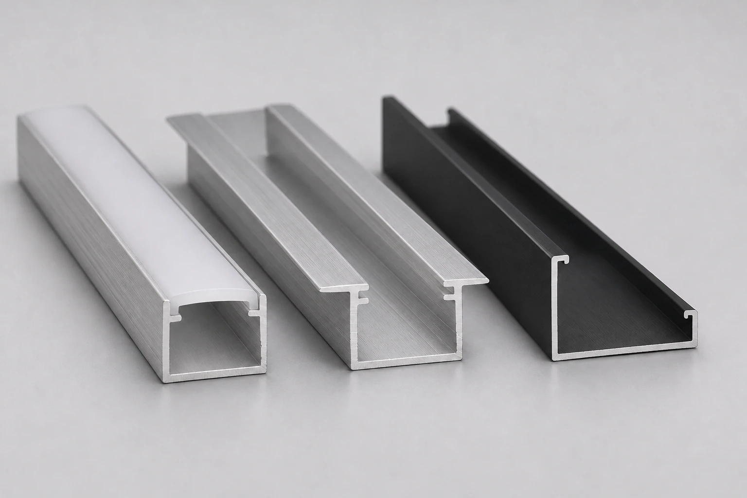
Surface, recessed and corner channel layouts with an opal diffuser.
Resolve fit, light appearance and installation before ordering
Specify an LED channel extrusion around three buyer decisions: what must fit inside, how the light should look and where the finished assembly will mount.
Will the strip and connector fit?
Compare usable cavity dimensions with the complete component envelope. A strip can fit while its connector prevents the cover from seating.
Which cover suits the light line?
Compare clear, frosted and opal options against the intended view, mixing distance and chosen strip. Review the actual assembly before approving appearance. [4]
Will the section suit the installation?
Check the substrate opening, fixing method, flange and maintenance access. Standard and custom sections can be specified around the project detail.
LED channel extrusion specifications
- Product category
- LED Channel Extrusions
- Profile family
- LED strip mounting channels
- Section options
- Surface, recessed, corner and custom sections
- Section system
- Application-specific section
Compare LED channel extrusion sizes and strip capacity
These four published section configurations provide practical starting points for selection. Outside dimensions and maximum strip width are separate measurements. The dimensions below follow the cited product table. [1]
| Selection parameter | Compact surface | Flanged recessed | Corner | Wide surface |
|---|---|---|---|---|
| Outside width × height | 12 × 7 mm | 17 × 15 mm | 16 × 16 mm | 30 × 20 mm |
| Maximum strip width | 8 mm | 12 mm | 10 mm | 20 mm |
| Mounting format | Surface-mounted | Recessed with flange | Corner; 45° light direction | Surface-mounted |
| Check before ordering | Strip and connector clearance | Routing size, flange and substrate | Corner clearance and light direction | Strip layout and cover fit |
APW can supply these section specifications and custom sizes. Confirm the final drawing, component interfaces and order requirements in the quotation; matching outside dimensions do not establish interchangeable covers or clips.
Read the LED channel extrusion dimensions that determine fit
Use these LED channel extrusion section and length views to identify the measurements needed for selection. This flanged layout explains dimension locations; obtain the numerical values from the selected drawing. A compact surface or corner section will have different mounting details. [2]
- Overall width
- Measure the complete section envelope, including flanges where present. This controls the visible footprint, not the usable strip bed.
- Overall height
- Check the complete height against the available installation space. Confirm any additional height required by clips or brackets separately.
- Usable mounting-bed width
- Check the finished bed where the strip and connector must sit. Include component tolerances and the agreed assembly allowance.
- Clear height below the cover
- Measure from the mounting bed to the cover underside. Check the tallest component, solder joint and cable bend, not just the strip thickness.
- Light-mixing distance
- Measure from the LED emitting surface to the cover underside. It is smaller than the full cavity height and must be considered with strip pitch and cover diffusion. [4]
- Substrate opening width
- Establish the opening from the selected body section and fixing method. Add only the installation clearance agreed for that drawing.
- Recess depth
- Check the space below the flange seating face. Include mounting hardware and cable routing in the installation detail.
- Flange overlap on one side
- Check the flange beyond the body on the illustrated side. Its overlap with the substrate depends on the actual opening and installed position.
- Finished aluminum length
- Dimension the cut metal separately from the overall assembly. End caps, joints and cover engagement can change the required component lengths.
LED channel extrusion fit example: a strip fits, its connector does not
Check LED channel extrusion fit by comparing the widest component with the finished usable bed before treating a nominal strip-width match as an assembly match.
- Assume a finished usable bed width of 12 mm, a maximum strip width of 10 mm and a maximum connector width of 13 mm.
- The connector must sit inside the same straight cavity; it cannot be moved outside the channel in this example.
- These are assumed example dimensions, not a supplied APW section. Height, cover retention and cable routing are separate checks.
Required component envelope = max(strip width, connector width) Width difference = usable bed width - required envelope
max(10, 13) = 13 mm 12 - 13 = -1 mm: the connector is 1 mm too wide 12 - 10 = 2 mm: total width difference for the strip alone
| Width check | Example value | Selection result |
|---|---|---|
| Finished usable bed | 12 mm | Space available at the component mounting plane |
| Maximum strip width | 10 mm | Leaves a 2 mm total width difference; this alone does not approve assembly |
| Maximum connector width | 13 mm | Exceeds the available width by 1 mm |
| Controlling envelope | 13 mm | The connector determines the width requirement in this example |
The 2 mm difference is total width difference, not clearance on each side and not a universal assembly tolerance. Use finished dimensions so the same finishing allowance is not subtracted twice.
This LED channel extrusion fails the width check for the assumed assembly. Choose another connector, revise the cable-exit arrangement or specify a wider cavity. Then check height, cover fit and the agreed assembly allowance; passing one width check does not establish complete compatibility.
Discuss your strip and connector dimensionsChoose a clear, frosted or opal cover
Choose an LED channel extrusion cover for the installed viewing position and required light appearance. Cover diffusion trades visible LED points against transmitted output; the actual result depends on the selected cover and strip combination. [4, 5]
| Cover appearance | Light appearance and trade-off | Typical selection context | Confirm with the sample |
|---|---|---|---|
| Clear | LED points remain more visible; prioritize transmission over blending. | Concealed runs where the reflected light is seen. | Visible points, reflections and the chosen cover profile. |
| Frosted | A diffusing surface changes the appearance of individual LED points; output and blending depend on the specific cover. | Runs needing some diffusion while retaining the required output. | Surface finish, point visibility and output with the actual strip. |
| Opal / milky | A more diffusing appearance can soften LED points, with an output trade-off. | Directly viewed light lines where uniform appearance is a priority. | Strip pitch, mixing distance, viewing angle and acceptable output. |
Frosted and opal names may overlap between suppliers. Approve the selected cover, material and interface; no universal transmission percentage or dot-free result applies to every LED channel extrusion.
Diagnose LED channel extrusion assembly problems
Start with the observed symptom, inspect the relevant interface and adjust the selected parts or installation detail. These checks guide investigation rather than setting universal product limits.
| Observed problem | Check first | Adjustment direction |
|---|---|---|
| Visible LED points | Strip pitch, emitting-surface-to-cover distance, cover diffusion and viewing angle. [4] | Trial a different cover, deeper mixing space or strip combination at the intended view. |
| Connector pushes against the cover | Maximum connector height and width, solder joints and cable bend. | Change the connector or exit arrangement, or select a cavity with suitable clearance. |
| Cover will not seat | Matching retention profile, orientation, finished section dimensions, cut-end damage and obstructions. | Use the matched cover and section; resolve the obstruction or dimensional mismatch before assembly. |
| Recessed assembly stands proud | Actual opening, recess depth, flange seating face, clips and cable path. | Correct the installation detail or select a section suited to the available depth. |
| Uneven joints or cover gaps | Cut lengths, end squareness, joint alignment and end-cap or cover engagement. | Revise the cut list or joint detail against the approved drawing and assembly conditions. |
| Operating temperature is too high | Strip load, mounting contact, enclosure, airflow and the specified temperature measurement conditions. [3] | Review the complete thermal path and evaluate the revised assembly under its intended conditions. |
Confirm the root cause on the actual assembly. Clip spacing, wattage limits, temperature limits and ingress ratings require the selected product and installation specification.
Build an LED channel extrusion quantity and accessory list
Turn an LED channel extrusion layout into finished component quantities before estimating raw-material purchases. This example counts independent runs, not a continuous line with intermediate joints.
- Assume 20 independent runs, each with a finished aluminum length of 1.2 m and an assumed finished cover length of 1.2 m.
- Each run has one cable-entry end cap and one closed end cap, with no intermediate joining pieces.
- The equal cover and metal lengths are an example assumption. The final cover length and end engagement must follow the selected assembly drawing.
Finished material length = number of runs × finished length per run Each end-cap type = number of independent runs
20 × 1.2 m = 24 m of finished aluminum 20 × 1.2 m = 24 m of finished cover 20 × 1 = 20 cable-entry caps; 20 × 1 = 20 closed caps 20 + 20 = 40 end caps in total
| Finished component | Example quantity | What determines the final order |
|---|---|---|
| Aluminum channel | 20 × 1.2 m = 24 m | Finished cut list, section and length tolerances |
| Matching cover | 20 × 1.2 m = 24 m | Cover engagement and end-cap detail on the approved drawing |
| Cable-entry end caps | 20 | One specified entry cap for each run |
| Closed end caps | 20 | One specified closed cap for each run |
| Mounting clips / supports | Determine for the selected system | Fixing design, substrate and approved support arrangement |
24 m is finished material demand, not the raw-stock purchase quantity. Calculate stock quantities from available lengths, saw kerf, trim losses and reusable offcuts. No common clip spacing is assumed.
Use this component list as a starting point for an LED channel extrusion RFQ. Keep metal and cover cut lengths separate, and identify the quantities of each end-cap type instead of requesting an unspecified accessory kit.
Send your cut list and accessory quantitiesProduct views
LED channel sections and surface details
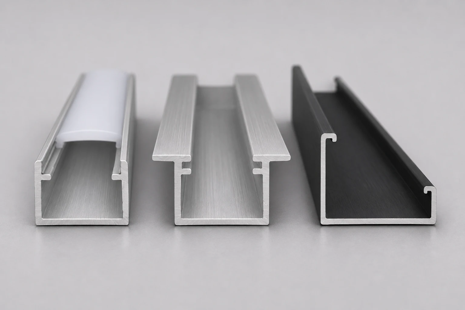
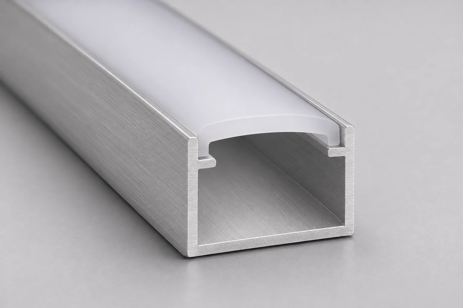
Match the chosen channel, cover and mounting accessories using the same section drawing and revision.
Confirm three decisions before requesting a quote
Use the LED channel extrusion guide above to resolve the component envelope, required light appearance and installation interface.
- Confirm the strip and connector envelope against finished cavity dimensions.
- Choose the strip-and-cover combination for the intended viewing position.
- Match the mounting format and service access to the installation detail.
Match the mounting style to the lighting detail
Select an LED strip profile around the available space, finished surface and maintenance access. The extrusion, lighting components and fixing arrangement need to work together.
- Surface-mounted cabinet and display runs
Use an exposed channel layout where the profile attaches to a finished surface. Include the fixing positions and cable route in the cabinet or display drawing.
- Flanged recessed lighting
Coordinate the routed opening, recess depth and flange with the joinery detail. Verify the dimensions from the selected cross-section rather than from the visible cover width.
- Corner lighting
Review a corner section where the light needs to point away from adjoining faces. Check the installed angle and available space at the actual corner.
- Plaster-in ceiling and wall lines
Choose a section intended for the approved plasterboard detail. Coordinate finishing edges, fixing access and cover removal before the wall or ceiling is closed. [2]
- Suspended linear assemblies
Identify the suspension interfaces, supports, joints and power feed on the assembly drawing. Specify the fixing design separately from the continuous aluminum section.
Prepare your LED channel extrusion order
Send the section reference or dimensioned drawing, finished lengths, quantity and delivery destination. Add the required alloy, temper, finish and color; published product families include 6063-T5 sections and different cover materials, but the selected specification must be identified for your order. [2] List the requested cutting, drilling, covers and accessories separately. Price, tooling, MOQ, packaging and delivery schedule are confirmed in the quotation.
Check fit before installing the LED channel extrusion
After selecting the LED channel extrusion, use this installation sequence with the approved drawing and component instructions.
Review the cross-section
Check the selected drawing against the dimension guide above, then verify fixing positions and the substrate opening.
Dry-fit the components
Trial the strip, connectors, cover, end caps and fixings together. Check cable routing and service access before installing the full run.
Prepare the mounting and strip bed
Check cut ends, edges and the mounting face. Install the strip using its specified method and keep the required contact area clean.
Check the completed assembly
Review cover seating, joints, light appearance and temperature under the intended conditions before approving repeat production. [3]
Define the LED channel extrusion accessories
List LED channel extrusion accessory references and quantities on the RFQ. Catalogs pair different sections with covers, end caps and mounting hardware; the quotation should state exactly which items are included. [2]
Diffuser or lens
Specify the cover material, appearance, length and retaining interface. Check a sample with the chosen strip before agreeing the required light appearance.
End caps and wire outlets
Identify closed and cable-entry ends. Provide cable dimensions and any required exit position so the end detail can be checked.
Clips, brackets and supports
List the mounting components and their quantities. Agree fixing positions for the substrate and assembly rather than assuming one spacing works for every run.
Joints and suspension parts
Show straight joints, changes of direction and any hanging interfaces on the layout. Confirm the selected hardware against the extrusion drawing.
A complete LED channel extrusion inquiry example
This sample buyer request turns the fit and quantity checks into specific RFQ requirements. It describes a hypothetical project, not an APW stock model or an approved installation.
- Installation
- Surface-mounted cabinet lighting; 20 independent runs, each with one cable-entry end and no intermediate joints.
- Strip and connector
- LED strip width: 10 mm. Connector envelope: 13 mm wide × 6 mm high; connector must fit inside the channel.
- Required finished cavity
- Usable bed width: at least 14 mm. Clear height below the cover: at least 7 mm. These are buyer requirements for this example, not default allowances for all channels.
- Metal and finish
- 6063-T5 aluminum, silver anodized. Request the selected section drawing for fit review.
- Finished cut list
- 20 aluminum pieces × 1,200 mm. Matching opal PC covers for all 20 runs; confirm final cover lengths and end engagement against the assembly drawing.
- End caps and supports
- 20 cable-entry end caps and 20 closed end caps matched to the selected section. Itemize the mounting clips and confirm quantities for the selected fixing system.
- Delivery and acceptance
- Destination: Rotterdam, Netherlands. Quote packaging and delivery terms; confirm the drawing revision, cut-length tolerance, component fit and appearance sample before order approval.
The 14 mm and 7 mm requirements belong to this assumed project. They are not supply tolerances or a general compatibility rule. Keep unresolved drawing, support and delivery details explicit in the quotation.
Discuss a comparable channel requirementAgree how the finished channels will be checked
Link acceptance to the approved drawing and component list, with any appearance or operating checks defined for the complete assembly.
Dimensions and finish
Inspect the agreed section dimensions, cut lengths, straightness, edge condition and finish against the specified revision and acceptance method.
Component fit
Check strip seating, connector clearance, cover retention, end-cap fit and the mounting interface using the agreed components.
Installed appearance and operation
Review joints, cover continuity and visible light points at the intended viewing positions. Record operating conditions when evaluating assembly temperatures.
LED channel selection resources
Consult the original specifications and technical guidance for the dimensions and selection principles cited above.
- [1] Unitop: aluminum LED channels and diffusersPublished outside dimensions, maximum strip widths, mounting formats and clear-versus-opal cover guidance.
- [2] SIRS-E: aluminum extrusion data sheetExamples of surface, recessed and plaster-in sections, material specifications, covers and mounting accessories.
- [3] Cree LED: thermal management of XLamp LEDsThe thermal path, board and interface considerations, heat sinks and assembly measurement methods.
- [4] Acolyte: masking diode visibility in LED fixturesHow strip pitch, lens diffusion, mixing distance, reflections and viewing angle affect visible LED points.
- [5] Diode LED: SLIM channel lens optionsClear, frosted and other lens options illustrating why appearance names and matching parts must be checked for the selected system.
LED channel extrusion questions
How do I choose the right LED channel extrusion size?
Compare the complete component envelope with the finished usable cavity. The fit example above shows why a 10 mm strip can fit while a 13 mm connector cannot. Check cover height, retention and cable routing separately.
Can an LED channel extrusion accept both COB and SMD strips?
Either construction may be considered, but the actual strip dimensions, connectors, operating requirements and strip-and-cover appearance must be checked. COB or SMD alone does not establish compatibility.
Will a frosted diffuser remove every visible LED dot?
No universal result follows from the cover name. Use the diffuser comparison above, then evaluate strip pitch, mixing distance and the chosen cover at the intended viewing position. [4]
Does the aluminum channel guarantee adequate LED cooling?
No thermal rating applies to every assembly. Review the complete thermal path, mounting contact, load and environment, then evaluate the assembled lighting product under its specified conditions. [3]
Is an LED channel extrusion waterproof?
Specify the required ingress protection for the assembled lighting product. A bare extrusion and a matching cover alone do not establish that rating. Include the end details, cable entries, joints and sealing requirements, and agree what testing or documentation is required.
Can I order custom LED channel extrusion lengths and sections?
Yes. Send the selected cross-section or custom drawing, material and finish requirements, separate metal and cover cut lists, quantity and destination. The quotation confirms tooling, requested operations, packaging, MOQ and delivery terms.
Are covers, end caps and mounting clips included?
Specify each accessory and quantity. The project example separates cable-entry caps, closed caps and mounting supports; the quotation defines the matched items supplied with your order.
Related aluminum lighting profiles
Bring the channel and lighting requirements together
Resolve the section fit, light appearance and mounting detail in one LED channel extrusion inquiry. Send your drawing, strip and connector sizes, cover requirement, cut list, quantity and destination to request a quotation.
Browse aluminum profiles