
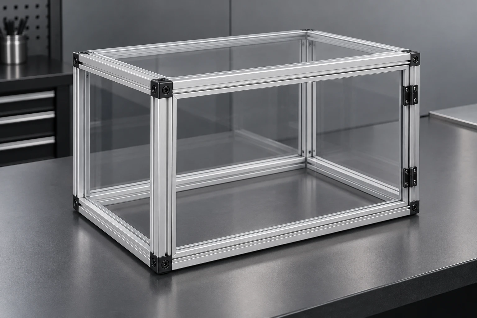
Small equipment enclosure frames
Confirm panel thickness and fixing method, door clearances, hinge locations and access for assembly. Include the enclosure layout and mating hardware in the inquiry.
Compact aluminum framing, specified for your assembly
APW supplies GB T-Slot 2020G Series aluminum profiles in the two listed versions for compact equipment enclosures, instrument racks and display frames. Choose the section that matches your layout and hardware, then send your cut lengths and quantities for a quote. Starting from an existing frame? Photos and basic measurements can begin the identification process.
No drawing? See how to identify your existing profile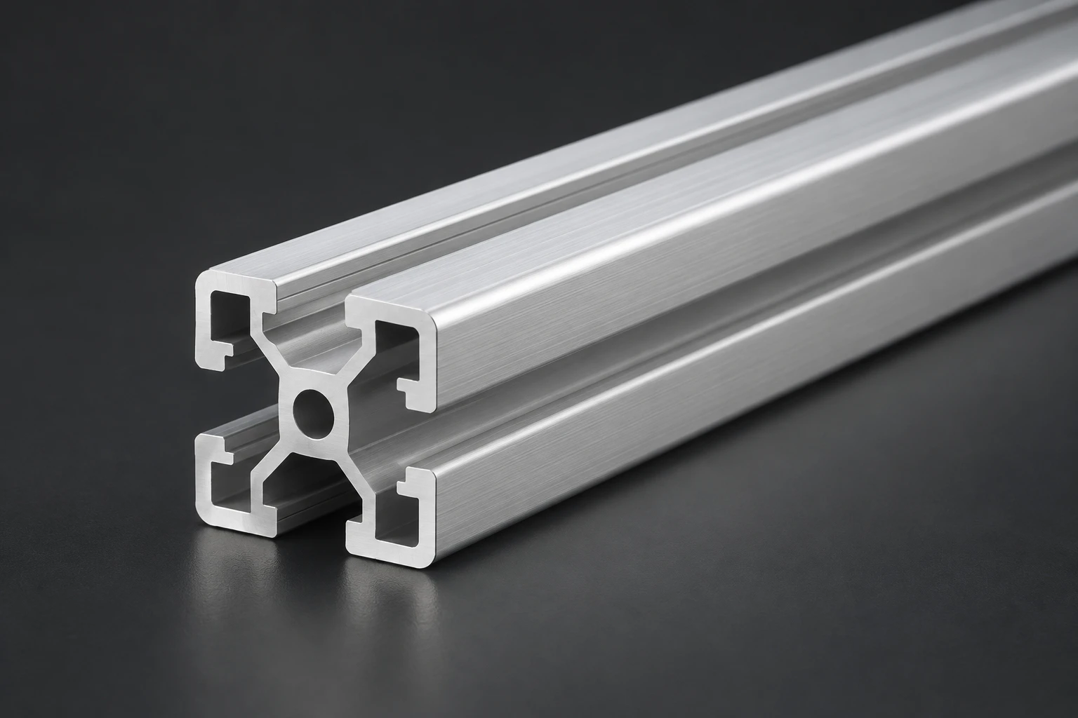
AI-generated product concept. Confirm the actual section and finish against the selected drawing.
Choose the right section and matching connections for your assembly. These benefits depend on the frame layout, the selected hardware and the agreed supply details.
Use the nominal 20 × 20 mm family as a compact framing option for small enclosures and supports. Check usable space after allowing for brackets, panels and doors.
Appropriate mechanical connections let you plan a frame that can be assembled, dismantled and adjusted. Confirm access to fasteners and the required joint design.
Keep the section drawing, hardware details and cut-length list together. Identifying those interfaces before ordering helps reduce wrong-part purchases and assembly rework.
APW can supply both listed versions. Choose one complete section specification: the wall thicknesses and other values below belong to separate variants. The slot-4 version has a documented square-slot interface; confirm the lightweight version’s unlisted interface dimensions against its selected drawing.
| Specification | Slot 4 — 1.3 mm wall | Light-wall — 0.75 mm wall |
|---|---|---|
| Cross-section | 20 × 20 mm | 2020 designation; confirm dimensions against selected drawing |
| Alloy and temper | 6063-T5 | 6063-T5 |
| Slot geometry | Square slot | Confirm against selected drawing |
| Slot series / opening | Slot 4 series / 4.3 mm opening | Confirm against selected drawing |
| Slot depth | 7.1 mm | Confirm against selected drawing |
| Center bore | Φ3.3 mm | Confirm against selected drawing |
| Wall thickness | 1.3 mm | 0.75 mm |
| Mass per meter | 0.434 kg/m | 0.34 kg/m |
| Published profile length | 6.02 m | 6.1 m |
| Surface treatment / color | Anodized / silver | Confirm against selected drawing |
| Connection reference | M4 square-nut connection reference; verify the selected hardware drawing | Confirm against section and hardware drawings |
Select one version and identify its drawing before ordering. The published lengths are profile-length references, not a universal cut-length limit. Silver anodizing is specified for the slot-4 version; agree the light-wall finish separately. Actual tolerances, processing, price and delivery terms are confirmed in the quotation. Technical model references are listed below. GB denotes the profile system here, not certification to a particular GB/T standard.
AI-generated product concepts
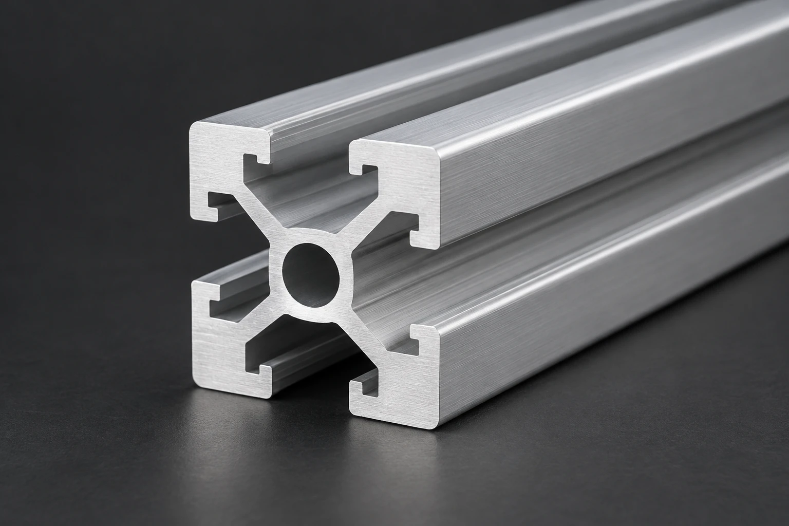
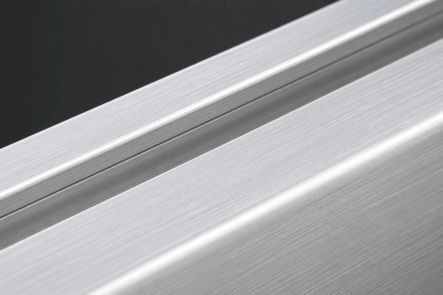
AI-generated product and surface concepts, not supplied-product photographs, measured sections or finish samples. Confirm the selected geometry and appearance using the drawing and an approved sample.
Treat GB 2020G, Euro 2020 and V-slot as separate interface choices until the actual drawings establish a match. A shared outer size or nominal slot name is insufficient.
Start with the space and connections your assembly needs. Review the three compact-frame applications below, then identify the section using its dimensions, loading and support conditions. These layouts do not establish a load rating.
Confirm panel thickness and fixing method, door clearances, hinge locations and access for assembly. Include the enclosure layout and mating hardware in the inquiry.
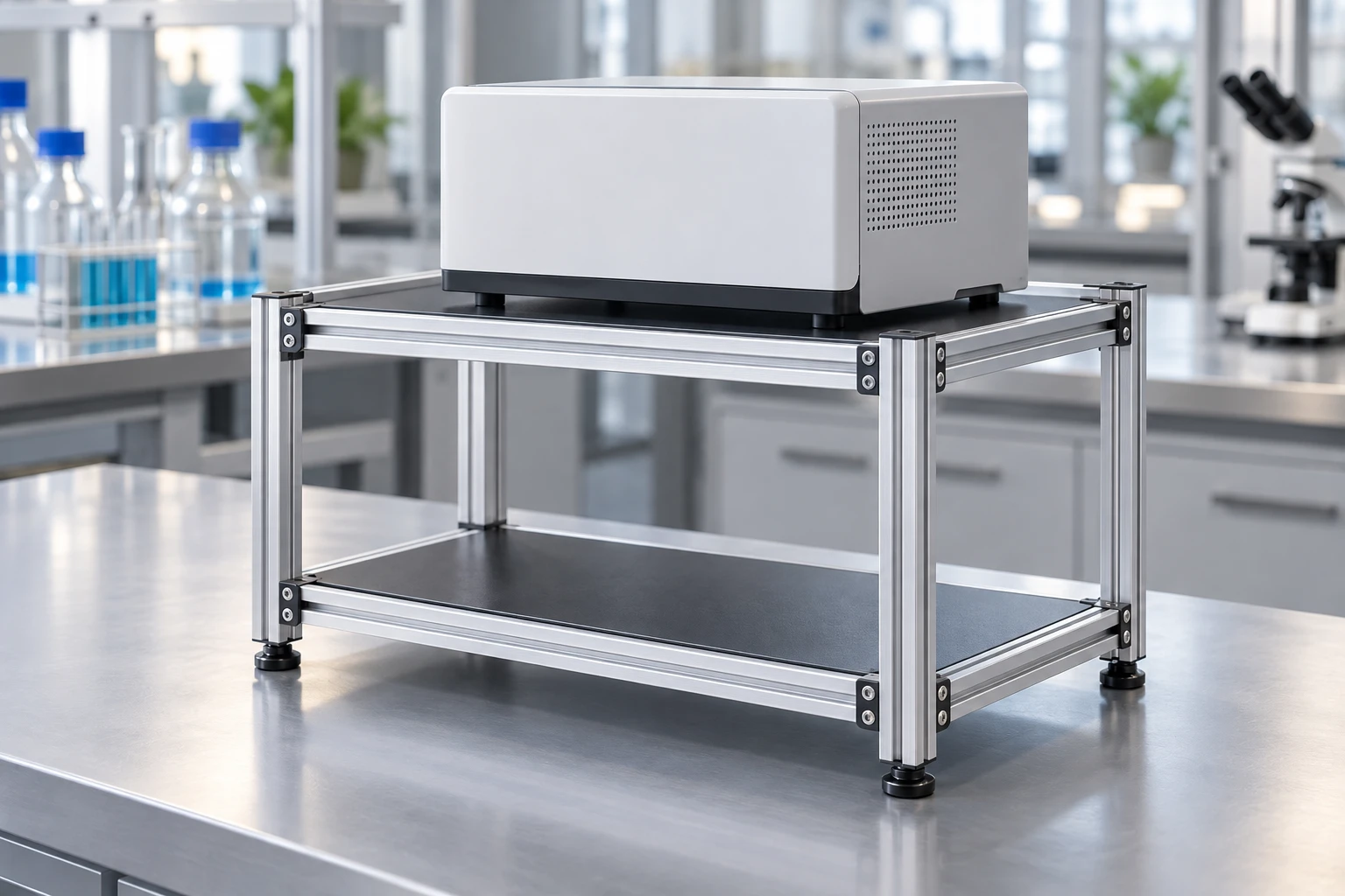
Provide equipment weight, support positions, unsupported spans and any vibration or alignment requirements. Review section properties and joints for the intended assembly.
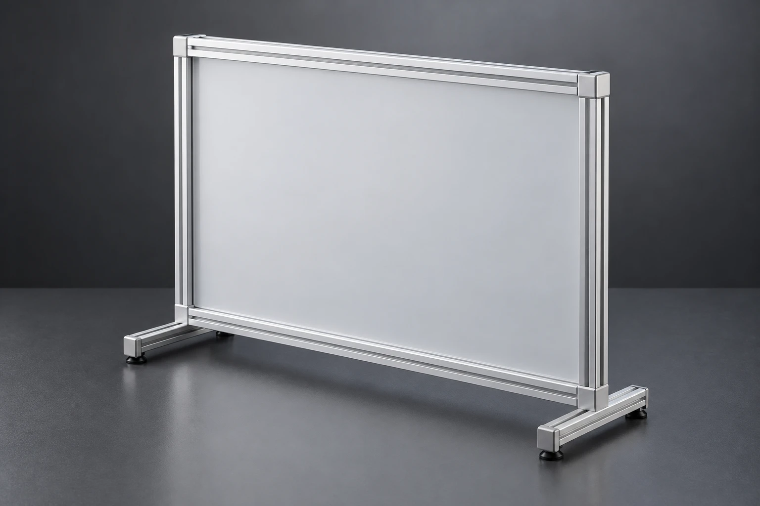
State the panel size, visible faces, appearance reference and how often the frame needs to be dismantled. Confirm feet, joints and panel fasteners together.
AI-generated application concepts only. These are not completed customer projects, tested assemblies or certified safety enclosures.
Send a selected drawing for a new frame, or photos and measurements for a replacement. The guides below help you identify missing details. Use the existing inquiry form or WhatsApp to start; drawings and photos can be shared through the existing contact channels. Processing requirements and commercial terms are reviewed during quotation.
For replacement parts or an unlabeled frame, send clear photos and basic measurements to begin identification. Keep a sample where possible; a 2020G name or photo alone does not establish a final match.
Show the whole cross-section square-on, in focus and without an obstructed edge. Include a ruler or other measurement reference and a separate close view of the slot.
Photograph the longitudinal faces, corners, joints and panel fixings. Include any markings or supplier model label that remains.
Measure outer width and height, slot opening, internal cavity and depth where accessible. Record the center-bore diameter and relevant wall measurements; mark anything you cannot measure.
Show the existing nut, bolt and bracket with dimensions or part numbers. Keep the original section and hardware available for comparison where fit is critical.
Photos and measurements support preliminary identification. Confirm the final replacement against an agreed drawing or sample before ordering.
Match each connection to the chosen section. The slot-4 version has an M4 square-nut connection reference; the thread designation alone does not establish that any particular nut or bolt will fit.
Compare nut width, height, body shape and thread with the groove cavity and lips. Confirm whether the nut is inserted from the end or can be installed after the frame is assembled.
Check the bracket or panel stack, nut position and bolt length together. Confirm adequate engagement and clearance from the groove base using the component drawings.
Check the bracket size, locating features, hole spacing and tool access. Confirm any section drilling or end machining before assigning a bracket.
State panel thickness, edge clearances and the fixing method. Coordinate hinges, retainers, seals or covers with the profile and door layout where applicable.
This is a drawing-review checklist, not a tested accessory compatibility list. Confirm named hardware part numbers or a trial fit for the selected assembly.
Use this fictional request as a format for your own specification. Replace the sample entries with your required section, drawing and quantities.
Example cut lengths are individual profile lengths, not finished frame dimensions. This example is not a default order, fixed tolerance, processing commitment or delivery promise.
Start your inquiry with the details you haveUse the order, approved drawing and agreed inspection requirements as the acceptance basis. Record discrepancies before assembly; this checklist does not introduce an additional tolerance standard.
Match the delivered profile identification and cross-section to the ordered version and approved revision. Keep the two variants separate during receiving and storage.
Count each length group and measure against the order’s agreed dimensions and tolerances. Keep piece labels or the packing list with the relevant group.
Check end condition, cut squareness and deburring against the agreed requirements. Record damaged ends or unexpected machining before use.
Check for transport damage, debris or obstructions in the grooves that could interfere with the agreed hardware or panel fixing.
Compare visible surfaces, color and treatment with the agreed finish and appearance reference. Document scratches, dents or inconsistent appearance.
Check the agreed nut, bracket and panel connection on a representative section before assembling the full frame. Stop and review any interference or unexpected play.
The following manufacturer documents provide technical references for the two listed section specifications. APW supplies the listed versions against the agreed specification; these links do not imply brand authorization, affiliation or universal hardware compatibility.
It is a nominal 20 × 20 mm profile family for compact modular frames such as small equipment enclosures, instrument racks and displays. APW supplies the two listed versions. Select the actual section, supports and connection design for your assembly; the family name alone gives no load rating.
Yes. Send a clear end-on photo, side and connection photos, outer dimensions and accessible groove measurements. Include existing hardware details or a supplier reference if available. These help begin identification; the final section is confirmed against an agreed drawing or sample.
Compare the original and proposed cross-sections, groove cavity, opening, depth, bore and mating hardware. Provide the existing nut or bracket dimensions and describe which parts must remain unchanged. Agree the replacement drawing or sample before ordering.
Slot-series names and measured openings are different specifications. Use the actual opening shown for the selected version in the comparison table and drawing. Do not assign the slot-4 geometry to the light-wall version without checking its own section.
Confirm nut body dimensions and insertion method, thread, bolt length and engagement, bracket locating features and hole positions, panel thickness and tool access. The M4 connection reference belongs to the slot-4 version; it is not blanket approval of Euro 2020, V-slot or another manufacturer’s accessories.
The listed versions are supplied in 6063-T5 aluminum. Silver anodizing is specified for the slot-4 version. Agree the light-wall version’s surface treatment and appearance reference separately. Identify the selected section and finish together in your inquiry.
Start with the selected version and drawing, or existing-profile identification information. Add a cut-length list with piece counts, finish, tolerances, hardware details, any processing drawing and destination. Use the worked example as a format. Price, processing feasibility, minimum order and delivery terms are confirmed in the quotation.
Compare the separate Euro 20 × 20 mm profile family and its own groove specification.
Review a 30 × 30 mm framing envelope with separate connection requirements.
Review the 40 × 40 mm family before changing frame size or mating hardware.
Have a drawing and cut list? Send them for a quote. Replacing an unknown profile? Start with photos, measurements and the connections you need to match.
Browse aluminum profiles