APW Aluminum Profile WorksExtrusions · Sourcing · Delivery
HomeProducts
Categories
Industrial Aluminum ProfilesA starting point for standard industrial profiles and drawing-led custom aluminum extrusion requirements.T-Slot Aluminum ExtrusionsReview the confirmed Euro 4040 T-slot profile, selection checks, applications and RFQ details for modular industrial framing.Aluminum Extrusion Heat SinksPrepare a heat sink profile inquiry with its section, airflow, mounting interface, thermal conditions and finished-part requirements.Aluminum Solar Mounting RailsPrepare a solar rail profile inquiry with its clamp channel, splice interface, material, finish and project requirements.Aluminum Enclosure ProfilesDefine an electronics enclosure profile around its PCB clearance, guide slots, end-panel interface, finish and machining requirements.Architectural Aluminum ProfilesPrepare a drawing-led inquiry for window, door, curtain-wall and shading extrusions with clear section, interface, finish and supply requirements.Aluminum Window ProfilesPrepare a drawing-led window profile inquiry around frame and sash sections, glazing and hardware interfaces, thermal construction and finished supply details.Aluminum Curtain Wall ProfilesPrepare a drawing-led curtain wall profile inquiry around mullion and transom sections, glazing and sealing interfaces, material, finish and finished supply requirements.Thermal Break Aluminum ProfilesPrepare a specification-led inquiry for thermal break aluminum sections with clear barrier interfaces, assembly responsibilities, finish and supply requirements.Aluminum Door ProfilesPrepare a drawing-led door profile inquiry around frame, leaf and threshold sections, hardware and sealing interfaces, thermal construction and finished supply details.LED Aluminum ProfilesPrepare an LED channel sourcing inquiry with clear strip and diffuser interfaces, mounting details, finished dimensions and supply requirements.Aluminum Trim ProfilesPrepare a drawing-led trim inquiry for panel edges, corners and floor transitions with clear section, fit, finish and supply requirements.
Materials
Anodized Aluminum ExtrusionsSource aluminum extrusion profiles with anodized finish options through Aluminum Profile Works. We coordinate profile sourcing, finishing requirements and export preparation for industrial buyers. Start with a listed profile or your drawing, then define the finish for the actual application.Powder Coated Aluminum ProfilesChoose powder coated aluminum profiles for your appearance, exposure and finished-fit requirements. Agree samples and critical dimensions before ordering to help reduce rework. Aluminum Profile Works coordinates profile sourcing, finishing requirements and export preparation from your catalog reference or drawing.6061 Aluminum ExtrusionSource 6061 aluminum extrusion to your specification. Send APW your drawing, temper and quantity to start a sourcing review.
About

Language

  • English
  • 简体中文
  • Español
  • Português
  • Français
  • Deutsch
  • Italiano
  • Bahasa Indonesia
  • 日本語
  • 한국어
  • العربية
  • Русский
  • ไทย
  • Türkçe
  • Nederlands
  • Polski
  • Tiếng Việt
  • हिन्दी
APW Aluminum Profile WorksExtrusions · Sourcing · Delivery

Specification-led aluminum profile sourcing, machining, finishing, quality communication and export preparation for industrial buyers.

Aluminum profile sourcing and quality coordination

Categories

  • Industrial Aluminum Profiles
  • T-Slot Aluminum Extrusions
  • Aluminum Extrusion Heat Sinks
  • Aluminum Solar Mounting Rails
  • Aluminum Enclosure Profiles
  • Architectural Aluminum Profiles
  • Aluminum Window Profiles
  • Aluminum Curtain Wall Profiles
  • Thermal Break Aluminum Profiles
  • Aluminum Door Profiles
  • LED Aluminum Profiles
  • Aluminum Trim Profiles

Quick Links

  • Home
  • About Us
  • Privacy Policy

Contact Us

sales@aluprofileworks.com
Chat on WhatsApp

Language

  • English
  • 简体中文
  • Español
  • Português
  • Français
  • Deutsch
  • Italiano
  • Bahasa Indonesia
  • 日本語
  • 한국어
  • العربية
  • Русский
  • ไทย
  • Türkçe
  • Nederlands
  • Polski
  • Tiếng Việt
  • हिन्दी

© 2026 Aluminum Profile Works. Requirements are confirmed for each project.

Home/Products/GB T-Slot 4040G Series

Plan the frame, its connections and the next modification

GB T-Slot 4040G Series

Plan workbench frames, machine guards and equipment supports with the GB T-Slot 4040G Series. These nominal 40 × 40 mm references include distinct slot geometries, wall thicknesses and published masses. Use the frame example, connection concepts and model table to define your cut list and mating hardware, then send APW your requirements for review. The selected drawing governs fit; every requested model requires quotation and supply confirmation.

Chat on WhatsApp
Replacing an existing profile? Start with identification
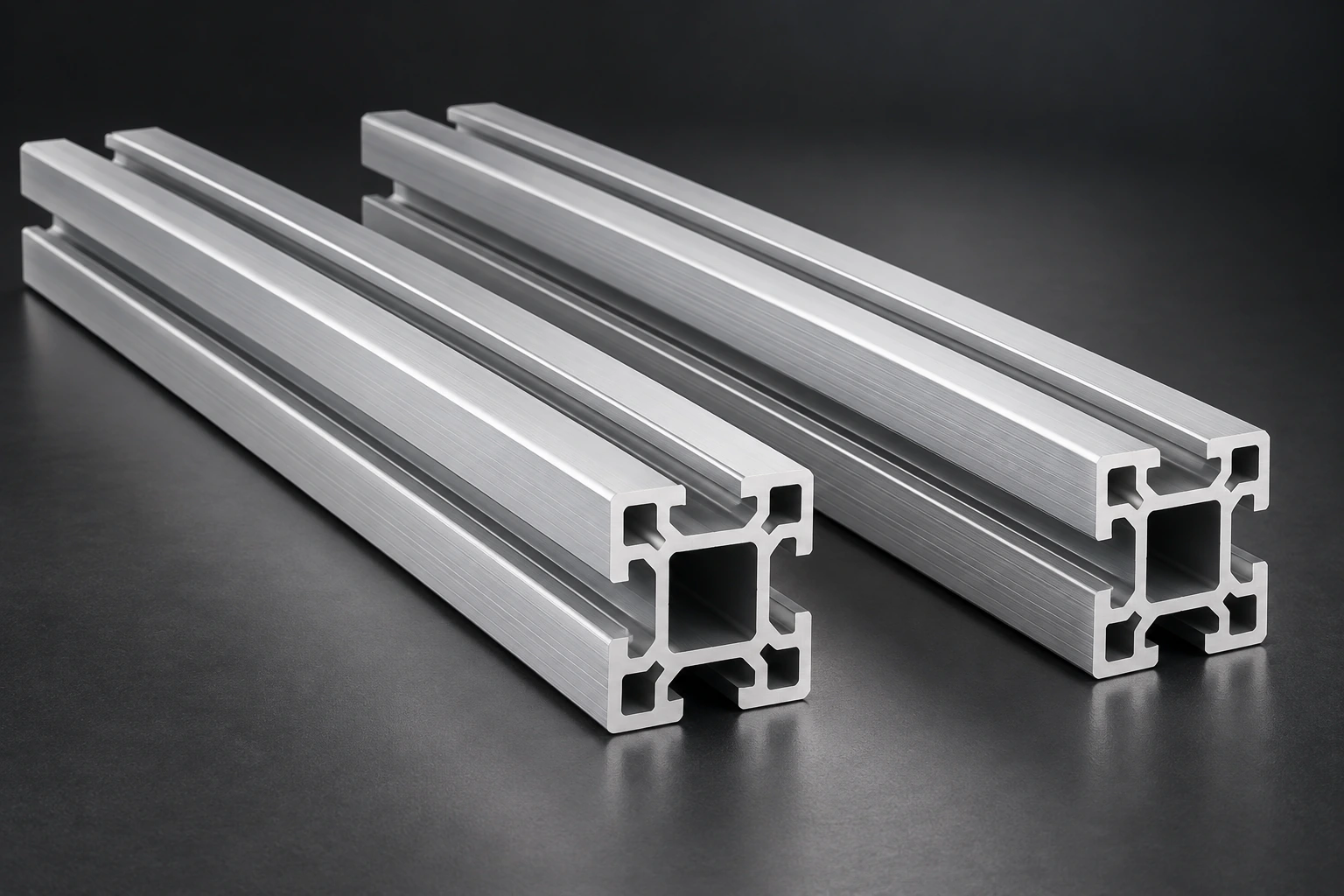
Two satin silver square-slot aluminum profiles arranged on a graphite studio surface

Concept view of square-slot aluminum profiles with clean edges and a satin silver surface.

Plan for assembly, mounting and later changes

Define the frame around its connections and intended use. The selected section and compatible accessories determine what the assembly can do.

Plan a modular assembly

Use a suitable profile and mechanical connection layout to plan an assembled frame. Confirm the joints and any required machining before ordering.

Locate panels and accessories

Use the selected groove interface with matching nuts, brackets and panel fixings. Check their seating, clearances and installation method.

Prepare for maintenance and changes

A suitably designed removable joint can support later dismantling or component replacement. Preserve the section and accessory records for future modifications.

4040G series overview

Profile category
T-Slot Extrusions
Profile series
GB 4040G
Nominal section and specification basis
40 × 40 mm nominal family; selected drawing defines the section
Profile system
GB profile family — confirm the selected interface

4040G model and specification references

These 11 published model references were identified in research checked on 20 October 2026; they are not an exhaustive market list or confirmed APW stock. Source numbers match the technical references below. Values belong only to their named source model. Drawing required means the field was not established in the reviewed material. Neither term means that the feature is absent.

4040G model and specification references
Source / published modelMaterial / temperSlot interfaceWall thicknessMass per meterReference lengthFinish / color
[1] Huishuo — HS-8-4040G6063-T5Square; 8.2 mm opening, 14 mm depth; no center hole3.0 mmConflicting published values — drawing confirmation required6.02 mAnodized / silver
[2] Huishuo — HS-8-4040GH6063-T5Square; 8.4 mm opening, 13.8 mm depth; Φ6.8 mm center hole3.5 mmConflicting published values — drawing confirmation required6.02 mAnodized / silver
[3] Huishuo — HS-8-4040GS6063-T5Square; 8.2 mm opening, 12.7 mm depth; Φ10 mm center hole3.0 mmConflicting published values — drawing confirmation required6.02 mAnodized / silver
[4] Huishuo — HS-8-4040GL6063-T5Square; 8.5 mm opening, 13.2 mm depth; Φ10.2 mm center hole1.8 mmConflicting published values — drawing confirmation required6.02 mAnodized / silver
[5] Huishuo — HS-8-4040GLL6063-T5Square; 8.8 mm opening, 13.8 mm depth; Φ10.6 mm center hole1.2 mmConflicting published values — drawing confirmation required6.02 mAnodized / silver
[6] Anteng — AT-8-4040G6063-T5Drawing required; source marks the section 40x40GADrawing required2.2 kg/m6.03 mDrawing required
[7] Anteng — AT-8-4040GB6063-T5Drawing requiredDrawing required2.4 kg/m6.03 mDrawing required
[8] Qiyu — QY-8-4040GA6063-T5Drawing requiredDrawing required1.48 kg/m6.01 mDrawing required
[9] Qiyu — QY-8-4040GB6063-T5Drawing requiredDrawing required1.22 kg/m6.01 mDrawing required
[10] Qiyu — QY-8-4040GW6063-T5Drawing requiredDrawing required2.15 kg/m6.01 mDrawing required
[11] E&I — ENI-8-4040GDrawing required8 mm slot listed; geometry drawing requiredDrawing requiredDrawing requiredDrawing requiredDrawing required

Every Huishuo square-slot page carries two different mass values for its model: a product specification and a separate GB4040Gx product-parameters block (HS-8-4040G 1.83 / 1.92, GH 1.22 / 1.38, GS 1.3 / 1.45, GL 1.04 / 1.12, GLL 0.73 / 0.79 kg/m). No value is adopted here. Qiyu additionally publishes section properties for its models: QY-8-4040GA Ix = Iy 9.25 cm⁴, Zx = Zy 4.86 cm³; QY-8-4040GB Ix 5.99 / Iy 6.53 cm⁴, Zx = Zy 3.0 cm³; QY-8-4040GW Ix = Iy 10.2 cm⁴, Zx = Zy 5.32 cm³. Published profile lengths are source references, not APW stock lengths or cutting limits. Equal mass does not establish equal geometry, stiffness or hardware fit. The G suffix is a supplier series code, not a national-standard designation, and GB describes the profile family on this page, not certification to a GB/T standard. All model references require a selected drawing and quotation confirmation.

Product gallery

4040G profile details and frame layout

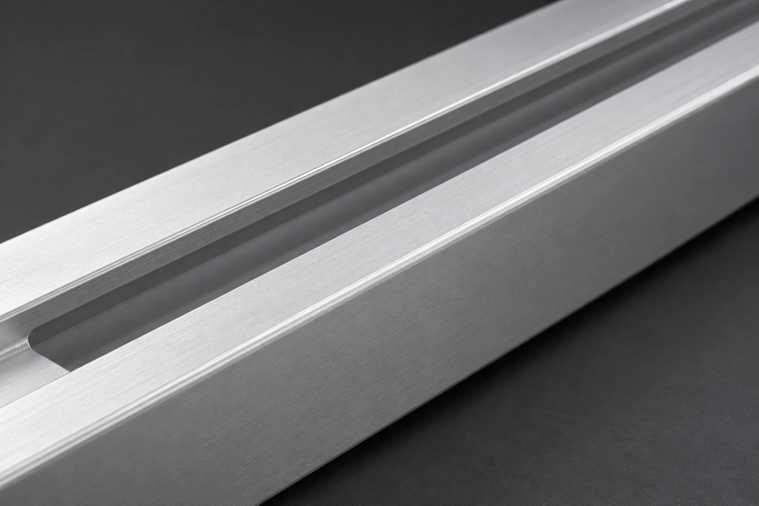
Close-up of a satin silver aluminum profile showing a recessed groove, fine longitudinal texture and a clean edge
Concept detail of the profile surface, recessed groove and precision edge.
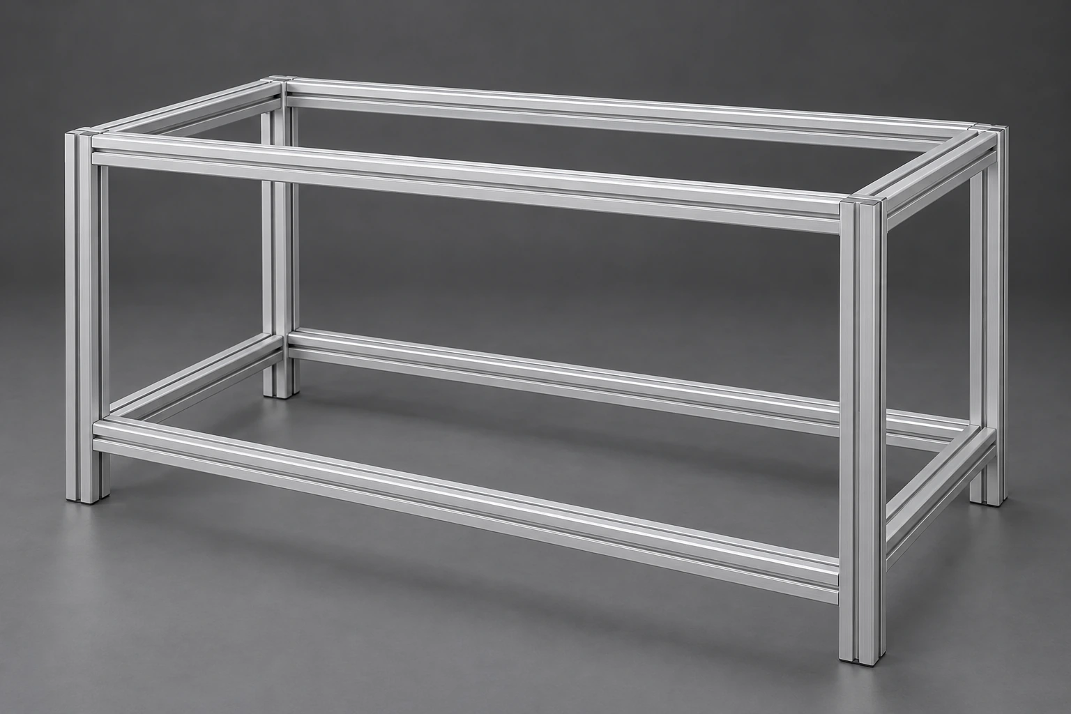
Silver aluminum workbench frame with four upright posts and upper and lower rectangular rail rings
Four-post workbench frame concept with eight rails; the final joint design requires confirmation.

Concept visualizations only, not verified supplier section or connection drawings. Confirm the actual section, surface finish and connections against the selected drawing and agreed sample.

Example: plan a four-post 4040G workbench frame

This fictional workbench layout illustrates material planning: four legs with upper and lower rail rings. Resolve the joint design before converting the draft into an order.

Topology concept only. The nodes identify connection positions, not a connector design. The sketch gives no finished outer dimensions, hole locations or load rating.
  • Orange lines: leg segments
  • Gray lines: upper and lower rails
  • Green points: connection positions to resolve
Example: plan a four-post 4040G workbench frame
ComponentPlanning quantityIndividual piece lengthSpecification to resolve
Leg segments4 pieces750 mmSelected section drawing and end interfaces
Long rails, upper and lower4 pieces1200 mmJoint layout and any end machining
Short rails, upper and lower4 pieces600 mmJoint layout and any end machining
Corner or end connectorsBy node designNot applicableConnection type and accessory drawing at each node
Nuts and boltsBy selected connectorNot applicableNut body, retention, bolt engagement and clearances

BOM draft for planning only. Accessory quantities and machining remain open until the node design is agreed. The listed lengths are individual cut segments, not finished frame dimensions; joint offsets and member placement can change the final outside size.

Three connection concepts to discuss

Use these relationship sketches to describe your assembly. None identifies a compatible part number or a universal connection for every 4040G profile.

External corner bracket

A bracket links two members at a corner. Consider tool access and clearance for adjacent panels.

Interface checks
Bracket seating, locating tabs, slot cavity, nut retention and bolt engagement.
Processing to clarify
Confirm the bracket drawing and insertion method before deciding whether additional access holes or other machining are needed.

Member end connection

One member connects at its end to another. Define the selected connector and the end interface together.

Interface checks
End interface, connector position, accessible slot geometry and assembly sequence.
Processing to clarify
The chosen connector may call for specified drilling, tapping or access machining. Use its machining drawing rather than assuming a standard hole.

Panel fixing

A fixing links a panel to the frame. Select it around the panel and the available profile interface.

Interface checks
Panel thickness, edge clearance, fixing spacing, slot fit and access for panel removal.
Processing to clarify
Clarify any panel holes, profile machining, spacers or seals after the fixing arrangement is selected.

Original concept diagrams, not manufacturing or installation drawings. Colors separate the members and connecting elements; their shapes and positions do not establish dimensions, compatibility or strength. Use selected profile and hardware drawings for the actual assembly.

Worked example: profile length and reference weight

The arithmetic below is a static planning example. It does not select a supply model or calculate the strength of the frame.

  1. 1. Add the individual cut lengths

    (750 mm × 4) + (1200 mm × 4) + (600 mm × 4) = 10200 mm = 10.2 m of net profile length.

  2. 2. Identify the mass reference

    For illustration, use the 1.48 kg/m published for Qiyu QY-8-4040GA, source [8]. This value belongs to that named source model and is not applied to the other 4040G references.

  3. 3. Estimate net profile mass

    10.2 m × 1.48 kg/m = 15.096 kg, approximately 15.1 kg of profile in this example.

Mass reference: Qiyu QY-8-4040GA product page [8]

This is net profile mass only. It excludes connectors, panels, packaging, cutting losses and unused stock. Purchased bar requirements depend on the agreed lengths and cutting arrangement. Confirm the selected drawing and actual supply specification; this example is not a shipping weight or cutting-service promise.

Choose the checks that fit your application

Use the application to decide which information to gather. These are planning prompts; no nominal series, wall thickness or mass alone establishes frame capacity.

Choose the checks that fit your application
ApplicationPlanning goalCritical dimensionsConnection checksInclude in your RFQ
Machine guard or safety enclosureSurround equipment and preserve access for operation and serviceGuard envelope, door openings, panel thickness, viewing areasPanel fixings, hinges, latches, seals and removal accessLayout drawing, door arrangement, panel material and any applicable site safety requirements
Workbench or workstation frameSupport the work surface and locate tools and accessoriesWorking height, top size, support spans, levelling interfaceLeg joints, top fixing, foot or caster interfaces and cross-bracing positionsTop material and mass, load positions, accessory list and floor-fixing needs
Conveyor or equipment supportCarry equipment at a defined height and alignmentSupport height, rail spacing, equipment footprint, adjustment rangeEquipment mounting interfaces, member joints and end connectionsEquipment mass, mounting drawing, alignment tolerances and vibration or movement expectations

Review the assembly and loads when selecting the section, spans and joints. Where stiffness, vibration or load capacity matters, use the relevant section and connection data for engineering review; no numeric capacity is inferred here.

Four ordering mistakes to avoid

Resolve these points before issuing the final cut list or accepting an alternative source model.

Using the frame envelope as the cut length

Possible consequence
The assembled outside size can be wrong once the member placement and joint offsets are included.
Better specification
Dimension the assembly, decide the joint layout, then issue a separate piece-length and quantity list.

Matching a nut by thread size alone

Possible consequence
Its body may not enter, seat or remain retained in the selected slot.
Better specification
Check nut dimensions, insertion method, cavity fit and bolt engagement against both drawings.

Treating equal names or mass as interchangeable

Possible consequence
The replacement can have a different groove, bore, wall layout or connection interface.
Better specification
Identify the manufacturer model and drawing revision; check the full section and mating hardware.

Treating catalog length as an available supply length

Possible consequence
The quoted bar or cut arrangement may differ from the purchase assumption.
Better specification
State required cut lengths, counts and delivery constraints, and agree the supply arrangement in the quotation.

What information shapes the quotation?

Quote requests become easier to compare when they define the same section, operations and delivery basis. Each item below is a requirement to discuss, not a confirmed APW service option.

01

Section and material basis

Identify one source model or drawing revision and the required material. Different sections can have different mass and supply bases.

02

Quantity and batches

Give piece counts by length and whether deliveries are split into batches. Avoid mixing pieces, meters and kilograms without a stated basis.

03

Cuts and material allowance

List the number and length of pieces. Ask how cutting losses and unused material are treated in the proposed supply arrangement.

04

Machining requirements

Describe any requested drilling, tapping or other processing with a drawing. Confirm feasibility, inspection and price in the quotation.

05

Surface requirements

State treatment, color and appearance criteria, with an approved sample reference where needed. A finish name alone may be insufficient.

06

Packaging and transport

Provide destination, handling constraints and packaging needs. Confirm the delivery basis and any separate freight charges.

Request a quote against a defined section

Send the source model and drawing revision, or provide photos and measurements for initial identification. Add piece lengths, quantities, finish requirements, any machining drawings and the delivery destination. APW will review the sourcing requirement; model availability, tolerances, processing, price and delivery terms are established in the quotation.

Identify an existing 4040G profile

A photograph can begin identification. Keep a sample or dimensioned drawing for the final match.

  1. 01

    Show a clean end view

    Photograph the section square-on beside a scale. Include the outer corners, internal webs and center bore, if present.

  2. 02

    Measure the interface

    Record the outside width and height, slot opening and accessible cavity dimensions. Note your measuring method and uncertainty.

  3. 03

    Include the mating parts

    Send the nut, bracket, bolt and panel-fixing references, with photos or drawings showing how they sit in the groove.

  4. 04

    Keep identifying records

    Include supplier labels, model markings, the old order or drawing revision. A 4040G suffix does not establish a cross-brand equivalent.

Check hardware before specifying a replacement

Confirm each interface against the selected profile and accessory drawings. Thread size alone cannot establish compatibility.

  1. 01

    Nut fit and retention

    Check the opening, undercut cavity, nut dimensions, seating surface and insertion method. Do not infer nut size from the nominal series.

  2. 02

    Bolt engagement

    Specify the bolt and required engagement for the selected connection. Check clearance and whether the connection needs end machining.

  3. 03

    Bracket location

    Check locating tabs, hole positions, contact faces and clearances. A bracket for Euro 4040 may not fit a GB square-slot section.

  4. 04

    Panels and moving parts

    Check the selected grooves against panel seals, covers, hinges and sliding components. Confirm with a sample assembly where fit remains uncertain.

Example 4040G RFQ — replace with your project details

This fictional example shows the information to include. It is not a stock offer, a minimum order or a confirmed frame design.

Section reference
GB 4040G family; match attached project drawing Rev A. Confirm the exact source model before ordering.
Individual cut lengths
Attach a final cut list with individual piece lengths, counts and the section drawing revision.
Material and finish
Propose material and finish against the selected section; agree a sample reference before order confirmation.
Cut and machining requirements
Square cuts; deburr ends. Quote any drilling or tapping separately against the attached machining drawing.
Mating hardware
Existing nuts and brackets shown in the attached photos; confirm fit against their drawings.
Acceptance requirements
Agree dimensional tolerances, finish acceptance and identification of each cut-length group in the quotation.
Delivery request
State destination postal code, packaging needs and requested date for quotation review.

Use individual cut lengths, not finished frame dimensions. Example quantities are explained in the frame-planning section; requested operations and delivery details require quotation confirmation.

Send your own 4040G requirement

Agree what to check at receipt

Use the confirmed order and drawing as the acceptance basis. Agree inspection methods and tolerances before ordering.

  1. 01

    Model and revision

    Match labels and packing records to the selected source model, section drawing and revision.

  2. 02

    Section and connections

    Check the agreed profile dimensions and representative mating parts. Document any mismatch before assembly.

  3. 03

    Lengths and counts

    Count each length group and measure against the agreed cut-length tolerances. Retain the group identification.

  4. 04

    Finish and cut ends

    Compare the surface with the agreed sample or appearance criteria. Check cut ends and any ordered machining.

Published model sources and evidence limits

Research checked on 20 October 2026. Numbers match the model table. These third-party references identify published models; they do not establish APW inventory, affiliation, authorization or interchangeable parts. Drawings and the confirmed order govern the selected supply.

  • [1] Huishuo — HS-8-4040GPublished square-slot geometry, 3.0 mm wall and silver anodized finish. The page shows 1.83 kg/m in its specification and 1.92 kg/m in a separate GB4040G parameters block; no value is adopted.
  • [1a] Huishuo — 40-series category listingCategory page where the five HS-8-4040G family models were identified. Read alongside sources [1]–[5]; the listing itself publishes no masses.
  • [2] Huishuo — HS-8-4040GHSquare-slot model with 3.5 mm wall and Φ6.8 mm center hole. Specification mass 1.22 kg/m conflicts with the 1.38 kg/m parameters block; confirm against a drawing.
  • [3] Huishuo — HS-8-4040GSSquare-slot model with 3.0 mm wall and Φ10 mm center hole. Specification mass 1.3 kg/m conflicts with the 1.45 kg/m parameters block; confirm against a drawing.
  • [4] Huishuo — HS-8-4040GLLightweight square-slot model with 1.8 mm wall and Φ10.2 mm center hole. Specification mass 1.04 kg/m conflicts with the 1.12 kg/m parameters block; confirm against a drawing.
  • [5] Huishuo — HS-8-4040GLLUltra-thin-wall square-slot model with 1.2 mm wall and Φ10.6 mm center hole. Specification mass 0.73 kg/m conflicts with the 0.79 kg/m parameters block; confirm against a drawing.
  • [6] Anteng — AT-8-4040GProduct page lists 6063-T5, 2.2 kg/m and 6.03 m, and marks the section 40x40GA. No slot geometry, wall or finish is adopted.
  • [7] Anteng — AT-8-4040GBProduct page lists 6063-T5, 2.4 kg/m and 6.03 m. No slot geometry, wall or finish is adopted; do not treat its values as describing AT-8-4040G.
  • [8] Qiyu — QY-8-4040GAProduct page lists 6063-T5, 1.48 kg/m, 6.01 m, Ix = Iy 9.25 cm⁴ and Zx = Zy 4.86 cm³. Slot geometry, wall and finish require the selected drawing.
  • [9] Qiyu — QY-8-4040GBProduct page lists 6063-T5, 1.22 kg/m, 6.01 m, Ix 5.99 / Iy 6.53 cm⁴ and Zx = Zy 3.0 cm³. Its asymmetric inertia values are not transferred to other models.
  • [10] Qiyu — QY-8-4040GWProduct page lists 6063-T5, 2.15 kg/m, 6.01 m, Ix = Iy 10.2 cm⁴ and Zx = Zy 5.32 cm³. Slot geometry, wall and finish require the selected drawing.
  • [11] E&I — ENI-8-4040G model referenceA 40 × 40 overview page lists ENI-8-4040G with an 8 mm slot and no technical parameters. Properties of adjacent E&I profiles are not applied to this model.

GB 4040G profile questions

What does GB T-Slot 4040G Series mean?

It is a purchasing reference for a nominal 40 × 40 mm profile family used in modular aluminum framing. Published 4040G models include square-slot and T-slot sections with different walls, cavities and finishes. The G suffix is a supplier series code, not a national-standard designation, a complete section specification or proof of GB/T certification.

How is GB 4040G different from Euro 4040?

Both names can refer to a nominal 40 × 40 mm outside section, but the groove opening, internal cavity, corner geometry and connection system can differ. Compare the actual drawings. A shared outer size does not establish interchangeable profiles or accessories.

Can I use the same nuts and brackets on every 4040G profile?

Do not assume compatibility. Check the opening, nut seating and retention, bracket tabs, bolt engagement and any end connection. Within the published Huishuo square-slot family alone, openings range from 8.2 to 8.8 mm with different depths and center holes. Use the selected profile and hardware drawings to confirm fit.

Why do 4040G mass and wall thickness values differ?

They belong to separate supplier models or section variants; the reviewed references span roughly 0.7 to 2.4 kg/m because they describe different sections. Keep the source model attached to each value. A single source can also contain inconsistent data: every Huishuo 4040G-family page shows two conflicting masses, so this page withholds a selected value pending drawing confirmation. Do not combine values from different listings.

What load can a 4040G aluminum frame carry?

This page does not assign a load rating. The required section depends on span, supports, connection design, load direction and allowable deflection. Qiyu publishes moments of inertia and section moduli for its three models, which are the kind of inputs an engineering review needs; mass per meter or the series name alone cannot determine frame capacity.

Are all listed models available from APW?

The table contains references you can submit for a sourcing inquiry. It is not an inventory or confirmed supply list. The exact model, selected drawing, material, finish, processing and delivery terms require quotation confirmation.

What should I send for a 4040G quotation?

Send the source model and section drawing or sample details, a separate cut list with individual lengths and quantities, finish requirements, the mating hardware or node drawings and the delivery destination. The frame example shows how to organize the components; replace its fictional quantities with your own. Photos and basic measurements can begin identification when a drawing is unavailable.

Are the published lengths the available cut lengths?

No. Published catalog lengths are source references, not APW stock records or cutting limits. Net cut-list length also differs from purchased bar requirements when losses or unused stock are involved. State the required piece lengths, quantities and delivery constraints so the quotation can confirm the supply arrangement.

Compare related profile families

GB T-Slot 3030G Series

Review the smaller nominal GB family with its own section and connection references.

GB T-Slot 2020G Series

Review the compact nominal GB family for lighter frames and fixtures.

Euro T-Slot 4040 Series

Compare a nominal 40 × 40 mm Euro family; check the interface before specifying accessories.

Discuss your 4040G requirement

Name the reference model and describe your drawing, cut lengths, quantities and destination. Supply and commercial terms are confirmed in the quotation.

GB T-Slot 4040G Series

GB 4040G

Chat on WhatsApp

Privacy Policy

After submitting, email drawings and open specification questions from the same address to sales@aluprofileworks.com

Your details are used only to prepare this inquiry. Drawings can be shared by email after contact.

Turn a 4040G reference into a defined RFQ

Send your section drawing or sample details with a cut-length list. Start with the interface you need and confirm the selected supply before ordering.

Chat on WhatsApp
Browse aluminum profiles