
Rectangular aluminum tube supply
Rectangular Tube 6063-T5
Source Rectangular Tube 6063-T5 for architectural details, display frames, furniture and fabricated assemblies. Compare 66 metric and inch sections, select mill, anodized or powder-coated finish, and send your dimensions and cut list to Aluminum Profile Works for a project quote.
Compare walls, orientation and fit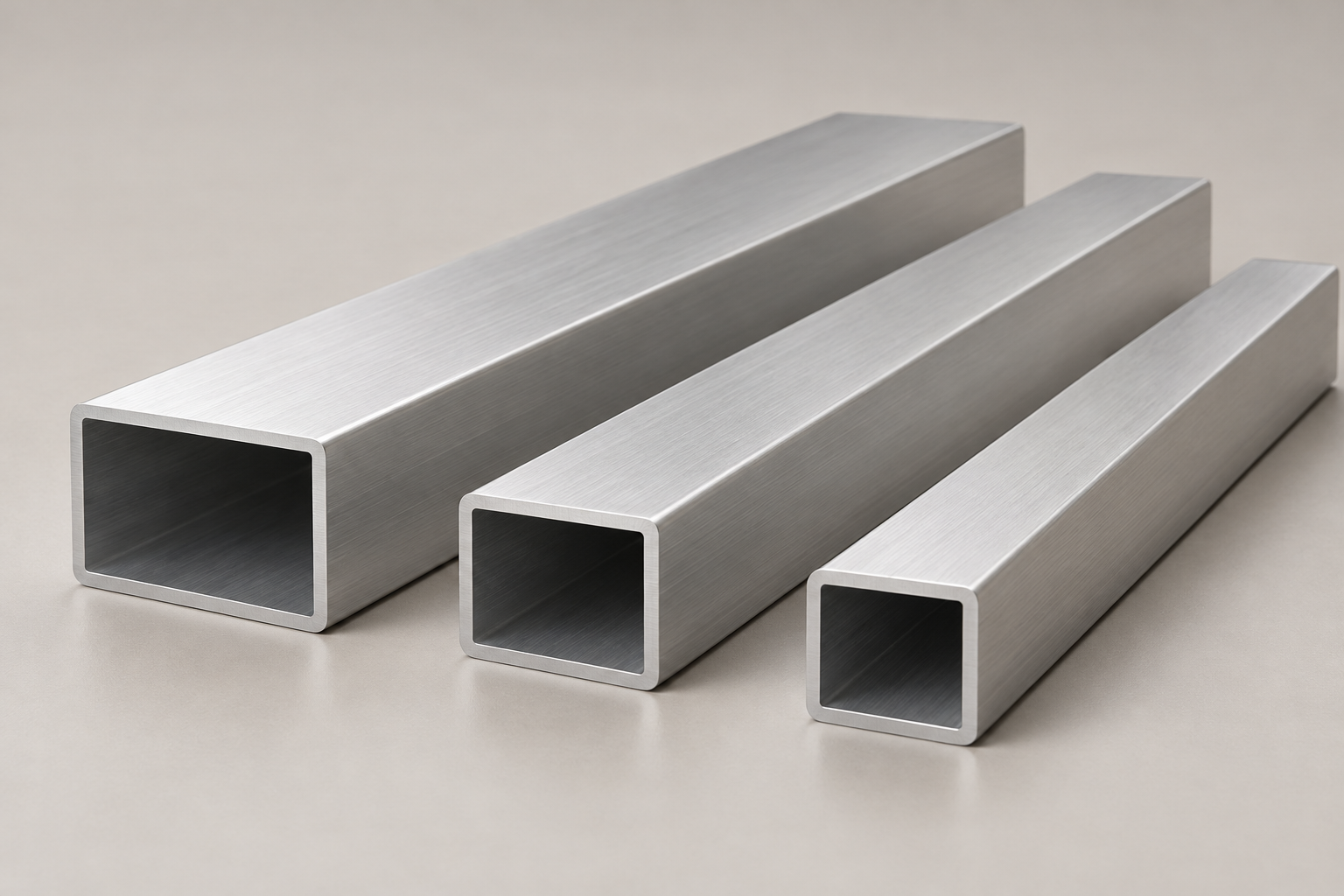
Unequal outside sides provide a broad face and a narrow face for positioning in an assembly.
Why specify Rectangular Tube 6063-T5?
Select the section geometry, material condition and finish as separate requirements. Together they define the component you need quoted.
Two different mounting faces
Rectangular Tube 6063-T5 offers a broad face and a narrow face around one hollow opening. Show which face supports a panel or connector, and locate holes from a defined datum on the drawing.
6063 for visible fabricated parts
6063 has good extrudability, surface quality, corrosion resistance and anodizing response. These material characteristics support appearance-led architectural and furniture components; the selected finish still needs an agreed appearance requirement. [4]
An identified material condition
T5 means cooling from an elevated-temperature shaping process followed by artificial aging. Rectangular Tube 6063-T5 is a material and section designation, not an assembly load rating or a statement of dimensional tolerance. [4]
Product information
- Profile category
- Aluminum Tubes
- Profile series
- Rectangular tube
- Section selection
- Unequal outside sides × wall thickness; discrete metric and inch sections
- Alloy
- 6063
- Temper
- T5
- Section system
- Universal section
Compare Wall Thickness, Opening and Weight
Start with the same 60 × 40 mm outside section and compare three available walls. A thicker wall increases material mass while reducing the space available to an internal fitting; it does not by itself establish the suitability of a complete assembly.
| Outside section × wall | Nominal inside opening (mm) | Theoretical mass (kg/m) | Mass change from 2 mm wall |
|---|---|---|---|
| 60 × 40 × 2 mm | 56 × 36 | 1.037 | Baseline |
| 60 × 40 × 2.5 mm | 55 × 35 | 1.283 | +23.7% |
| 60 × 40 × 3 mm | 54 × 34 | 1.523 | +46.9% |
The ideal area is AB − (A − 2t)(B − 2t); nominal mass is area × 0.0027 kg/m for dimensions in mm. The unrounded masses are 1.0368, 1.2825 and 1.5228 kg/m. Percentage changes use those unrounded values; displayed masses are rounded to three decimals using decimal half-up rounding. Actual corner radii, tolerances and coating affect opening and mass. Compare wall thickness with the joint, span and installed orientation rather than treating the percentage as a load-capacity gain.
Why Rectangular Tube Orientation Matters
For a 40 × 20 × 2 mm Rectangular Tube 6063-T5 section, rotating the long side changes the cross-section geometry relative to the bending axis. Both views below use the same downward force direction F and a horizontal centroidal x-axis. This compares section geometry, not a rated load.
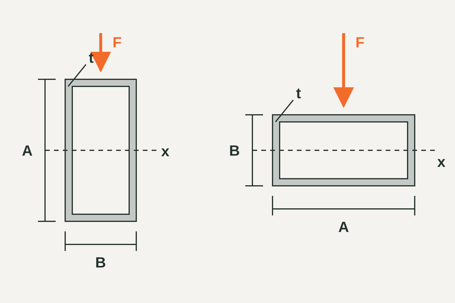
| Section orientation | Vertical depth h (mm) | Horizontal width b (mm) | Ideal Iₓ (mm⁴) | Iₓ relative to 20 mm depth |
|---|---|---|---|---|
| 40 mm side vertical | 40 | 20 | 44,458.67 | 3.09× |
| 20 mm side vertical | 20 | 40 | 14,378.67 | 1.00× |
For the uniform-wall, sharp-corner model, Iₓ = [b h³ − (b − 2t)(h − 2t)³] / 12 about the horizontal centroidal x-axis. The ratio uses unrounded values. It is not a 3.09× strength or safe-load claim: span, support conditions, load type, connections and acceptable deformation must also be defined. Actual corner geometry changes section properties. Reference [5] shows rectangular-tube data with both sectional axes; its tolerances and machining services are not APW specifications.
Check Inserts, End Caps and Corner Clearance
A 40 × 20 × 2 mm section has a nominal 36 × 16 mm opening before corner, tolerance and surface-treatment effects. An insert that clears both straight walls can still interfere at the internal corners. Check the complete mating contour rather than comparing only two nominal dimensions.
Straight-wall clearance, corner interference
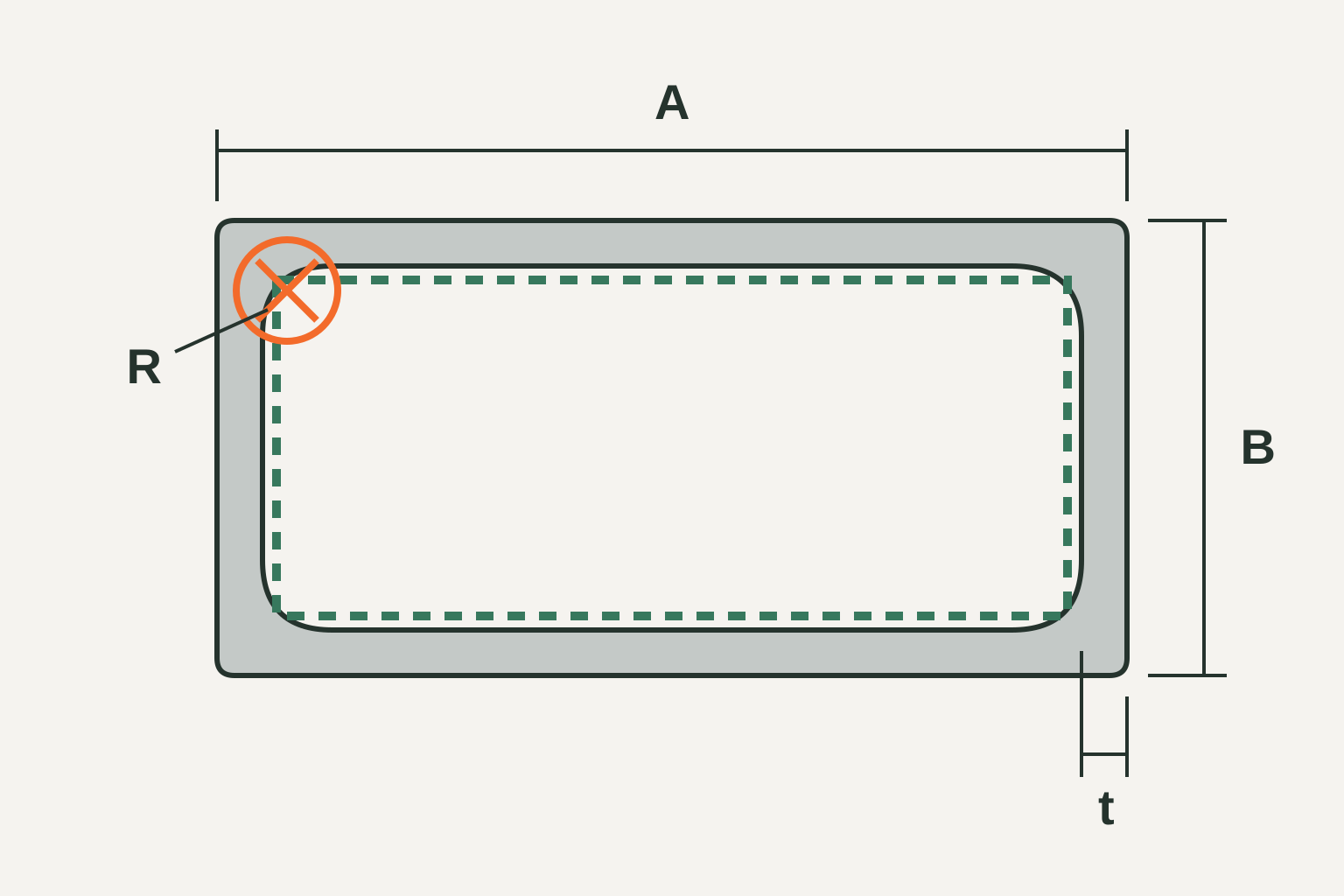
Corner relief with a clearance check
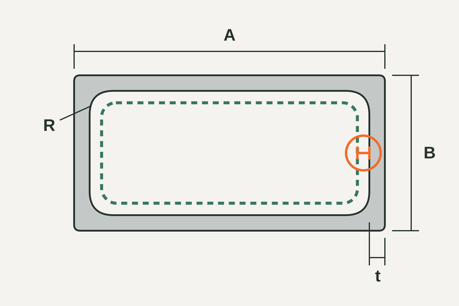
- Tube wall
- Mating insert outline
- Area requiring a fit check
- Check the long and short inside dimensions independently. For a uniform-wall model, the tightest straight-wall opening comes from the smallest allowed outside dimensions combined with the largest allowed wall thickness.
- Compare actual internal corner geometry with the full insert or end-cap outline, including its corner relief; the drawing symbol R does not specify a supplied radius.
- Identify whether fit dimensions apply before or after finishing. Anodizing can change dimensions, and total oxide thickness is not simply the outward growth on each surface. Agree the actual process and final dimensions. [6]
- State the required clearance, mating-part tolerances and any masked surfaces in the RFQ. Supply both mating drawings when a dimensional fit is critical.
These drawings explain contour relationships without assigning production radii, tolerances or coating thickness. A nominal 36 × 16 mm opening does not establish the largest insert that will fit; agree the finished geometry and acceptance method.
Plan Stock Length, Saw Kerf and Offcuts
Continue the worked RFQ for 40 × 20 × 2 mm Rectangular Tube 6063-T5: 20 finished pieces at 1,000 mm each. For this calculation only, assume 6,000 mm stock, 10 mm loss at each end and a 3 mm saw kerf for each finished piece separated from the bar. The end losses already include the associated trim-cut kerfs.
| Material balance | One assumed 6,000 mm bar | Four bars for 20 finished pieces |
|---|---|---|
| Raw length | 6,000 mm | 24,000 mm |
| Finished output | 5 × 1,000 = 5,000 mm | 20 × 1,000 = 20,000 mm |
| Finished-piece separation kerf | 5 × 3 = 15 mm | 20 × 3 = 60 mm |
| End losses, including trim-cut kerf | 2 × 10 = 20 mm | 8 × 10 = 80 mm |
| Remaining offcut length | 965 mm | 3,860 mm |
| Finished-length utilization | 83.3% | 83.3% |
Each bar balances as 6,000 = 5,000 + 15 + 20 + 965 mm. Six finished pieces would need 6,000 + 18 + 20 = 6,038 mm under these assumptions, so they do not fit. The full order balances as 24,000 = 20,000 + 60 + 80 + 3,860 mm. Finished-length utilization is 20,000 / 24,000, not a mass, price or production-yield guarantee. Ideal finished tube mass remains 12.096 kg; the assumed 24 m of raw tube is 14.5152 kg before actual corner, tolerance and coating effects. Packaging and shipping mass are separate. Stock length and cutting parameters are example assumptions to confirm during quotation; they do not establish a standard supply length or machining service.
Rectangular Tube 6063-T5 size chart
All 66 discrete Rectangular Tube 6063-T5 sections below are available for quotation. Each row is one outside-dimension × outside-dimension × wall combination from the explicit T5 tables in [1]–[3]. Retain its original unit in your RFQ; the sources identify geometry, not APW inventory or delivery terms.
| Original section / source | Outside A × B (mm) | Wall t (mm) | Nominal inside A × B (mm) | Theoretical mass (kg/m) |
|---|---|---|---|---|
| 15 × 10 × 1.2 mm [1] | 15 × 10 | 1.2 | 12.6 × 7.6 | 0.146 |
| 18 × 12 × 1.2 mm [1] | 18 × 12 | 1.2 | 15.6 × 9.6 | 0.179 |
| 20 × 15 × 1.5 mm [1] | 20 × 15 | 1.5 | 17 × 12 | 0.259 |
| 25 × 15 × 1.5 mm [1] | 25 × 15 | 1.5 | 22 × 12 | 0.300 |
| 1 × 0.5 × 0.063 in [2] | 25.4 × 12.7 | 1.6002 | 22.1996 × 9.4996 | 0.302 |
| 1 × 0.5 × 0.093 in [2] | 25.4 × 12.7 | 2.3622 | 20.6756 × 7.9756 | 0.426 |
| 1 × 0.5 × 0.125 in [2] | 25.4 × 12.7 | 3.175 | 19.05 × 6.35 | 0.544 |
| 30 × 10 × 1.5 mm [1] | 30 × 10 | 1.5 | 27 × 7 | 0.300 |
| 30 × 15 × 2 mm [1] | 30 × 15 | 2 | 26 × 11 | 0.443 |
| 30 × 20 × 2 mm [1] | 30 × 20 | 2 | 26 × 16 | 0.497 |
| 1.5 × 0.75 × 0.125 in [2] | 38.1 × 19.05 | 3.175 | 31.75 × 12.7 | 0.871 |
| 1.5 × 1 × 0.095 in [3] | 38.1 × 25.4 | 2.413 | 33.274 × 20.574 | 0.765 |
| 1.5 × 1 × 0.125 in [2] | 38.1 × 25.4 | 3.175 | 31.75 × 19.05 | 0.980 |
| 40 × 20 × 2 mm [1] | 40 × 20 | 2 | 36 × 16 | 0.605 |
| 40 × 30 × 2 mm [1] | 40 × 30 | 2 | 36 × 26 | 0.713 |
| 40 × 30 × 3 mm [1] | 40 × 30 | 3 | 34 × 24 | 1.037 |
| 50 × 25 × 2 mm [1] | 50 × 25 | 2 | 46 × 21 | 0.767 |
| 2 × 1 × 0.063 in [2] | 50.8 × 25.4 | 1.6002 | 47.5996 × 22.1996 | 0.631 |
| 2 × 1 × 0.095 in [3] | 50.8 × 25.4 | 2.413 | 45.974 × 20.574 | 0.930 |
| 2 × 1 × 0.125 in [2] [3] | 50.8 × 25.4 | 3.175 | 44.45 × 19.05 | 1.198 |
| 2 × 1.5 × 0.12 in [3] | 50.8 × 38.1 | 3.048 | 44.704 × 32.004 | 1.363 |
| 2 × 1.5 × 0.125 in [2] | 50.8 × 38.1 | 3.175 | 44.45 × 31.75 | 1.415 |
| 2.25 × 1.75 × 0.125 in [2] | 57.15 × 44.45 | 3.175 | 50.8 × 38.1 | 1.633 |
| 60 × 25 × 2 mm [1] | 60 × 25 | 2 | 56 × 21 | 0.875 |
| 60 × 30 × 2 mm [1] | 60 × 30 | 2 | 56 × 26 | 0.929 |
| 60 × 40 × 2 mm [1] | 60 × 40 | 2 | 56 × 36 | 1.037 |
| 60 × 40 × 2.5 mm [1] | 60 × 40 | 2.5 | 55 × 35 | 1.283 |
| 60 × 40 × 3 mm [1] | 60 × 40 | 3 | 54 × 34 | 1.523 |
| 2.5 × 1.25 × 0.125 in [2] | 63.5 × 31.75 | 3.175 | 57.15 × 25.4 | 1.524 |
| 2.5 × 1.5 × 0.12 in [3] | 63.5 × 38.1 | 3.048 | 57.404 × 32.004 | 1.572 |
| 70 × 30 × 2 mm [1] | 70 × 30 | 2 | 66 × 26 | 1.037 |
| 70 × 30 × 3 mm [1] | 70 × 30 | 3 | 64 × 24 | 1.523 |
| 70 × 35 × 2 mm [1] | 70 × 35 | 2 | 66 × 31 | 1.091 |
| 3 × 1 × 0.12 in [3] | 76.2 × 25.4 | 3.048 | 70.104 × 19.304 | 1.572 |
| 3 × 1 × 0.125 in [2] | 76.2 × 25.4 | 3.175 | 69.85 × 19.05 | 1.633 |
| 3 × 1.5 × 0.12 in [3] | 76.2 × 38.1 | 3.048 | 70.104 × 32.004 | 1.781 |
| 3 × 1.5 × 0.125 in [2] | 76.2 × 38.1 | 3.175 | 69.85 × 31.75 | 1.851 |
| 3 × 1.5 × 0.188 in [2] | 76.2 × 38.1 | 4.7752 | 66.6496 × 28.5496 | 2.701 |
| 3 × 1.75 × 0.125 in [2] | 76.2 × 44.45 | 3.175 | 69.85 × 38.1 | 1.960 |
| 3 × 1.75 × 0.188 in [2] | 76.2 × 44.45 | 4.7752 | 66.6496 × 34.8996 | 2.865 |
| 3 × 2 × 0.12 in [3] | 76.2 × 50.8 | 3.048 | 70.104 × 44.704 | 1.990 |
| 3 × 2 × 0.125 in [2] | 76.2 × 50.8 | 3.175 | 69.85 × 44.45 | 2.069 |
| 80 × 40 × 2.5 mm [1] | 80 × 40 | 2.5 | 75 × 35 | 1.553 |
| 100 × 50 × 2.5 mm [1] | 100 × 50 | 2.5 | 95 × 45 | 1.958 |
| 4 × 1 × 0.125 in [2] | 101.6 × 25.4 | 3.175 | 95.25 × 19.05 | 2.069 |
| 4 × 1.5 × 0.125 in [2] | 101.6 × 38.1 | 3.175 | 95.25 × 31.75 | 2.286 |
| 4 × 1.75 × 0.125 in [2] | 101.6 × 44.45 | 3.175 | 95.25 × 38.1 | 2.395 |
| 4 × 2 × 0.12 in [3] | 101.6 × 50.8 | 3.048 | 95.504 × 44.704 | 2.408 |
| 4 × 2 × 0.125 in [2] [3] | 101.6 × 50.8 | 3.175 | 95.25 × 44.45 | 2.504 |
| 4 × 2 × 0.187 in [3] | 101.6 × 50.8 | 4.7498 | 92.1004 × 41.3004 | 3.665 |
| 4 × 2 × 0.25 in [2] | 101.6 × 50.8 | 6.35 | 88.9 × 38.1 | 4.790 |
| 4 × 3 × 0.125 in [2] | 101.6 × 76.2 | 3.175 | 95.25 × 69.85 | 2.940 |
| 4.5 × 1.75 × 0.125 in [2] | 114.3 × 44.45 | 3.175 | 107.95 × 38.1 | 2.613 |
| 5 × 1 × 0.125 in [2] | 127 × 25.4 | 3.175 | 120.65 × 19.05 | 2.504 |
| 5 × 2 × 0.125 in [2] | 127 × 50.8 | 3.175 | 120.65 × 44.45 | 2.940 |
| 6 × 1 × 0.125 in [2] | 152.4 × 25.4 | 3.175 | 146.05 × 19.05 | 2.940 |
| 6 × 2 × 0.125 in [2] | 152.4 × 50.8 | 3.175 | 146.05 × 44.45 | 3.375 |
| 6 × 2 × 0.187 in [3] | 152.4 × 50.8 | 4.7498 | 142.9004 × 41.3004 | 4.968 |
| 6 × 2 × 0.25 in [2] | 152.4 × 50.8 | 6.35 | 139.7 × 38.1 | 6.532 |
| 6 × 3 × 0.125 in [2] | 152.4 × 76.2 | 3.175 | 146.05 × 69.85 | 3.810 |
| 6 × 3 × 0.188 in [2] | 152.4 × 76.2 | 4.7752 | 142.8496 × 66.6496 | 5.648 |
| 6 × 4 × 0.25 in [2] | 152.4 × 101.6 | 6.35 | 139.7 × 88.9 | 8.274 |
| 8 × 2 × 0.125 in [2] | 203.2 × 50.8 | 3.175 | 196.85 × 44.45 | 4.246 |
| 8 × 2 × 0.25 in [2] | 203.2 × 50.8 | 6.35 | 190.5 × 38.1 | 8.274 |
| 8 × 4 × 0.25 in [2] | 203.2 × 101.6 | 6.35 | 190.5 × 88.9 | 10.016 |
| 10 × 2 × 0.125 in [2] | 254 × 50.8 | 3.175 | 247.65 × 44.45 | 5.117 |
Rows use A as the longer outside side and B as the shorter side; this display order does not define the installed orientation. Inch dimensions use exactly 25.4 mm/in. Inside dimensions are A − 2t and B − 2t. Mass uses [AB − (A − 2t)(B − 2t)] × 0.0027 with dimensions in mm and nominal density 2,700 kg/m³. Values are rounded for display only; mass uses decimal half-up rounding to three decimals. The model assumes sharp corners and uniform walls; actual radii, tolerances and coatings affect opening and mass. These are discrete combinations, not a continuous size range.
Product views
Rectangular tube shape, opening and surface
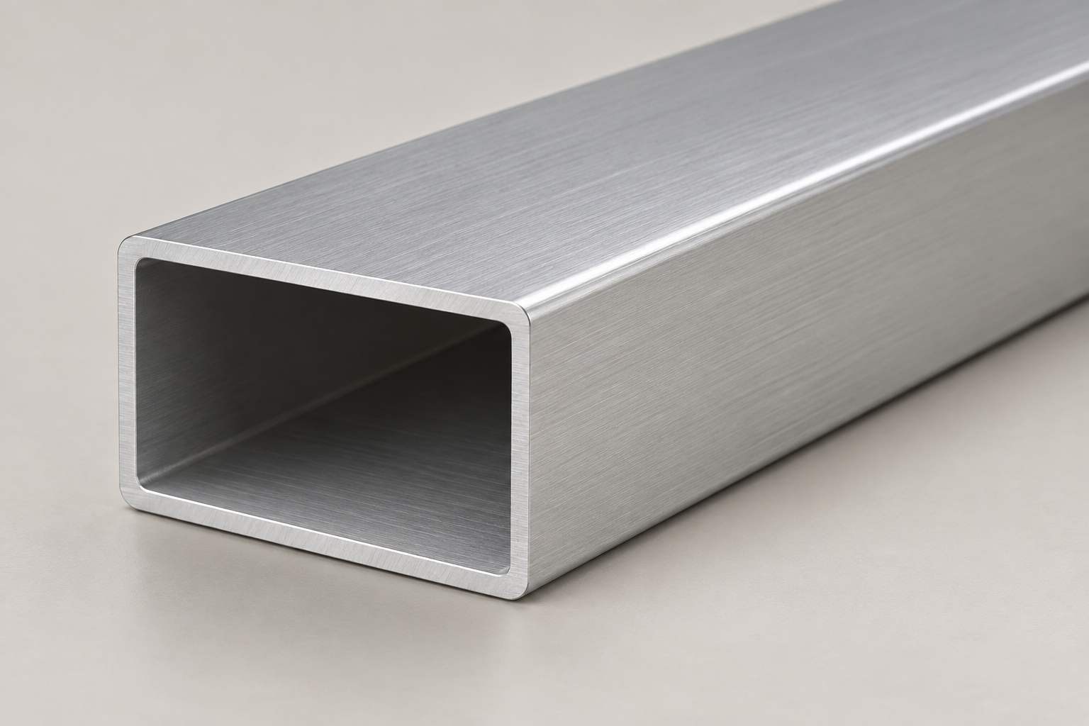
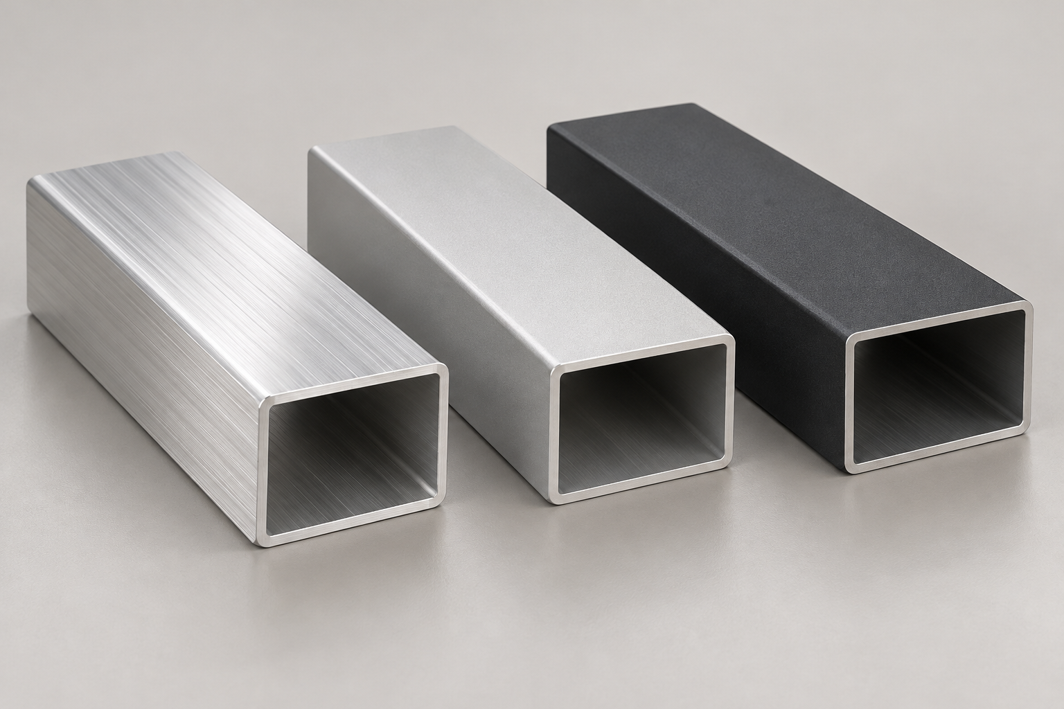
Appearance does not establish alloy, temper, dimensions or tolerances. Agree the section drawing, exposed faces and finish sample with your quote.
Estimate rectangular tube weight from your cut list
Use a geometry calculation for preliminary material planning. It is an estimate of the tube itself, not a shipping weight, measured piece weight or structural assessment.
Calculate the hollow section area
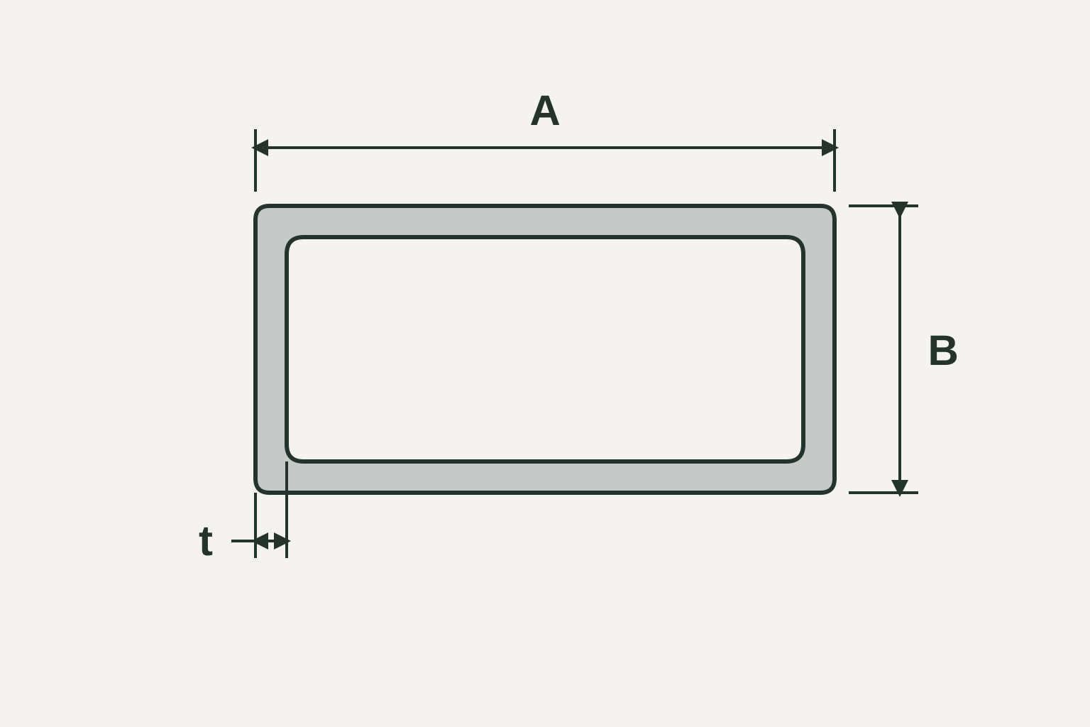
For outside dimensions A and B and a uniform wall t, area = AB − (A − 2t)(B − 2t). A 40 × 20 × 2 mm section has a nominal opening of 36 × 16 mm and an ideal area of 224 mm².
Convert area to mass per metre
Using nominal aluminum density 2,700 kg/m³, mass = 224 × 0.0027 = 0.6048 kg/m. This Rectangular Tube 6063-T5 estimate excludes the effect of actual corner radii, coating and manufacturing variation.
Multiply by total finished length
For 20 pieces at 1,000 mm each, finished length = 20 m. Ideal theoretical mass = 0.6048 × 20 = 12.096 kg, or about 12.10 kg. The stock-length example above accounts separately for kerf, end losses and offcuts.
Compare theoretical mass on a consistent geometry and density basis. A supplier's published or measured mass may use different corner geometry; do not substitute it silently into this calculation.
Choose the section around the installed orientation
Use the comparisons above to narrow your Rectangular Tube 6063-T5 choice, then confirm the remaining assembly requirements on the drawing.
- Identify the mounting face and hole datums for the installed orientation.
- Check the connection design, edge conditions and fastener access for the selected wall.
- Agree finished mating dimensions and any acceptance check with the quote.
Surface finish options
- Mill finish
- Anodized
- Powder coated
Where rectangular aluminum tube can be considered
These scenarios explain how unequal flat faces can help a design. Suitability depends on the complete assembly and its agreed requirements, rather than the material name alone.
- Architectural details and display frames
Rectangular Tube 6063-T5 can provide flat visible members for signage frames, partitions and display supports. Identify exposed faces, corner joints and finish matching before quotation; support and fixing requirements remain drawing-specific.
- Furniture and interior framework
Use the broad face for the intended attachment and define how the hollow ends will be closed. Include connector drawings, edge conditions and appearance samples where the tube is visible in the finished assembly.
- Panels and fabricated enclosures
Rectangular Tube 6063-T5 can be considered for panel surrounds and fabricated members needing different face widths. Specify hole datums, joint details and access for fasteners; do not assume compatibility with slotted framing hardware.
Define what the quotation must cover
Specify the complete section and native units, finished lengths and quantities, finish and delivery destination. Include the drawing revision, installed orientation, fit requirements and any required material or inspection documents. Ask for the raw supply length and cutting allowances to be confirmed separately from the finished cut list.
Identify outside dimensions, bore and material
Use a section drawing to remove ambiguity from a Rectangular Tube 6063-T5 enquiry. A tube described only as '40 × 20' leaves wall thickness, length and fit unresolved.
Outside sizes and wall thickness
State both outside dimensions and the nominal wall, with mm or inches. For example, 40 × 20 × 2 mm is one specific section; the 2 mm wall must not be inferred from another tube with the same outside sizes.
Internal opening and corners
Record both nominal inside dimensions and the mating contour on the drawing. Use the fit illustrations above to identify corner interference, then specify the finished-part tolerances and clearance required by your assembly.
T5 is distinct from T6 and T52
Request Rectangular Tube 6063-T5 by its complete designation. T6 uses solution heat treatment and artificial aging; T52 is a separate temper designation. Do not accept a substitution based only on shared outside dimensions or appearance. [4]
Cut length and drawing orientation
List the length and quantity of each finished part. Include end squareness, hole positions, datum faces and any miter angles on the current drawing rather than relying on the A/B order in the size chart.
Agree connection and finish details
Rectangular Tube 6063-T5 has plain closed walls, not accessory slots. Define the connection and finishing sequence around the actual assembly.
Fasteners, inserts and end caps
Provide connector dimensions, hole sizes and locations, engagement requirements and access needs. Attach the insert or end-cap drawing so that both sides and the corner contour can be checked together.
Mill, anodized or powder-coated finish
All three finishes are available for Rectangular Tube 6063-T5. Specify color, texture, exposed faces and required coating thickness or finish standard; agree masking where a fit or contact surface needs protection.
Fabrication and surface sequence
State whether drilling, cutting or joining is required before or after finishing. Agree the condition of cut edges and repaired surfaces rather than assuming they will match the coated outer faces.
Material and weld requirements
6063 can be welded, but a general alloy description does not qualify a joint. Include any joint preparation, finished condition and verification requirements in the drawing and quotation review. [4]
Rectangular Tube 6063-T5 RFQ example
Use this worked cut list as a format for your own requirement. Replace the project-specific choices and attach the corresponding drawing before sending.
- Material and section
- 6063-T5; 40 × 20 × 2 mm outside dimensions and wall
- Finished cut list
- 1,000 mm × 20 pieces; 20 m total finished length
- Finish requirement
- Silver anodized; agree appearance sample, coating requirement and exposed faces
- Drawing and fit
- Attach current revision; identify orientation, corner radii, end condition and any mating parts
- Acceptance requirements
- Specify required dimensional tolerances, material standard and inspection documents
- Delivery information
- Provide delivery country, city or port and packaging requirements
Ideal theoretical finished mass is 224 mm² × 0.0027 × 20 m = 12.096 kg (about 12.10 kg). Use the stock-length example above to distinguish the finished cut list from raw tube input. Neither value is a measured shipment weight.
Send your rectangular tube cut listCheck the agreed requirements on receipt
Compare Rectangular Tube 6063-T5 against the accepted quotation and drawing. Define inspection criteria before ordering, so the material, dimensions and appearance have a shared reference.
Material identity and documents
Match the alloy and temper designation, order identification and any agreed inspection documents. Appearance alone cannot distinguish 6063-T5 from another alloy or temper.
Section and finished length
Check both outside dimensions, wall thickness, straightness, cut length and end condition against the agreed tolerances and measurement method. Verify fit with the specified mating component where required.
Surface and packing condition
Compare exposed faces with the agreed finish sample and coating requirements. Check for transport damage and whether the agreed packing protects contact faces and open ends.
Section sources and material reference
The numbered references identify the source of published section dimensions and alloy guidance. APW supply of the listed sections and three finish types is confirmed separately; another supplier's stock, prices and services are not APW commitments.
- [1] Washin: A6063S-T5 hollow sectionsThe unequal-side rows supply 21 discrete metric sections. Equal-side square sections are excluded.
- [2] Aluminum Supply Company: 6063-T5 extrusionsThe rectangular tube mill and anodized tables supply 35 unique inch sections after repeated lengths and finishes are consolidated.
- [3] Russel Metals: 6063-T5 rectangular tubingTwelve discrete inch-size rows, excluding three range summaries. Two sections also appear in [2]; published weights are not substituted for calculated mass.
- [4] Hydro: alloy 6063 data sheetMaterial characteristics, temper definitions and condition-dependent property guidance; this is not an APW batch test report.
- [5] MISUMI: rectangular tubing section dataA reference presentation of both sectional moments of inertia for rectangular tubes. APW example values are independently calculated with the stated ideal geometry; supplier tolerances and fabrication services are not adopted.
- [6] BWC Profiles: anodizing and dimensional changeExplains why oxide thickness and outward growth per surface differ, and why final fit dimensions should be agreed for the selected process.
Rectangular Tube 6063-T5 questions
What does Rectangular Tube 6063-T5 mean?
It identifies a hollow rectangular aluminum section made from alloy 6063 in the T5 condition. T5 describes cooling from an elevated-temperature shaping process followed by artificial aging; it does not specify section dimensions, finish or dimensional tolerances. [4]
Which sizes can I request?
The chart lists 66 discrete Rectangular Tube 6063-T5 sections in native metric or inch dimensions. Each combination is available for quotation. For a dimension outside the chart, send a section drawing for review rather than assuming every intermediate size is a listed section.
Are the dimensions outside or inside sizes?
The original sizes in the chart are outside dimensions A × B followed by wall thickness t. Nominal inside dimensions are A − 2t and B − 2t. Check actual corner radii, tolerances and coating when an internal fit matters.
Can I treat an inch size as the nearest metric size?
Keep the original unit when ordering Rectangular Tube 6063-T5. One inch is exactly 25.4 mm, so a 2 × 1 × 0.125 in section converts to 50.8 × 25.4 × 3.175 mm; it is not a nominal 50 × 25 × 3 mm section. Rounded display values must not decide whether two sections are identical.
Does turning the section change how it performs?
Rotating an unequal-side section changes its relationship to the applied load and attachments. State the installed orientation, span, joints and service conditions for design review. This page does not assign a safe working load to the tube or assembly.
How is theoretical weight calculated?
Subtract the ideal internal rectangle from the external rectangle, then multiply the area in mm² by 0.0027 to obtain kg/m at nominal density 2,700 kg/m³. Multiply by total length in metres. Actual corner radii, tolerances and coating can change the result.
Which surface finishes are available?
Rectangular Tube 6063-T5 is available in mill, anodized and powder-coated finishes. Specify the appearance, exposed faces and coating requirements in your enquiry. The finish images show surface character; agree a sample where color or texture matching is important.
Can T6 or T52 replace T5?
Do not substitute a temper solely because the section dimensions match. T5, T6 and T52 are separate designations. Confirm the required material condition, applicable specification and assembly requirements before accepting a change. [4]
What should I send for a quotation?
Send the complete Rectangular Tube 6063-T5 designation, outside dimensions, wall thickness, native units, cut lengths and quantity per length. Include finish, drawing revision, tolerances, inspection requirements and delivery destination. Add the mating component drawing when an insert or connector fit is critical.
Are price, stock and delivery fixed by the size chart?
No. The chart identifies available section combinations, not live inventory or a price list. The quotation confirms price, order quantity, production details and delivery timing for the requested finish, cut list and destination.
Compare other aluminum tube sections
Square Tube 6063-T5
Compare equal-side hollow sections when both outside faces need the same width.
Round Tube 6063-T5
Compare circular hollow sections for components specified by outside diameter and wall.
Round Tube 6063-T6
Review a different section and temper as a separate requirement, rather than a direct T5 replacement.
Specify your Rectangular Tube 6063-T5 requirement
Choose a section from the metric and inch chart, define the finish and fit, and send your cut list. APW can quote Rectangular Tube 6063-T5 against your drawing, quantity and delivery requirements.
Browse aluminum profiles